
Mechanical emergency controls for hydraulic lifting systems on emergency rescue vehicles

An emergency control device and emergency rescue technology, which is applied in the direction of transportation and packaging, load suspension components, etc., can solve the problems of inability to respond to emergency rescue vehicles quickly, safely and efficiently, so as to recover people's property losses and ensure personal safety , the effect of saving rescue time

Active Publication Date: 2022-07-15
YANSHAN UNIV
View PDF0 Cites 0 Cited by
  • Summary
  • Abstract
  • Description
  • Claims
  • Application Information

AI Technical Summary

Problems solved by technology

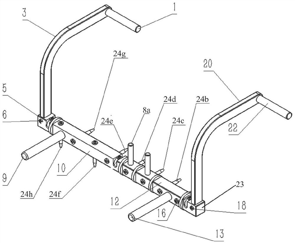
[0003] In view of the above situation, the present invention provides a mechanical emergency control device for the hydraulic lifting system on the emergency rescue vehicle, which solves the problem that the prior art cannot respond to emergency rescue vehicles on the construction site in an emergency, fast, safe and efficient manner. For the problem of emergency rescue, the combined control of the electromagnetic switch of the electro-hydraulic control cabinet on the emergency rescue vehicle through the operating handle of the control device is beneficial to the lifting, loading, handling, braking and emergency response of the hydraulic lifting system on the emergency rescue vehicle. stop function

Method used


Image

  • Mechanical emergency controls for hydraulic lifting systems on emergency rescue vehicles
  • Mechanical emergency controls for hydraulic lifting systems on emergency rescue vehicles
  • Mechanical emergency controls for hydraulic lifting systems on emergency rescue vehicles

Examples


Embodiment Construction

[0033] In order to detail the technical content, structural features, achieved objectives and effects of the present invention, the following will be described in detail with reference to the accompanying drawings.

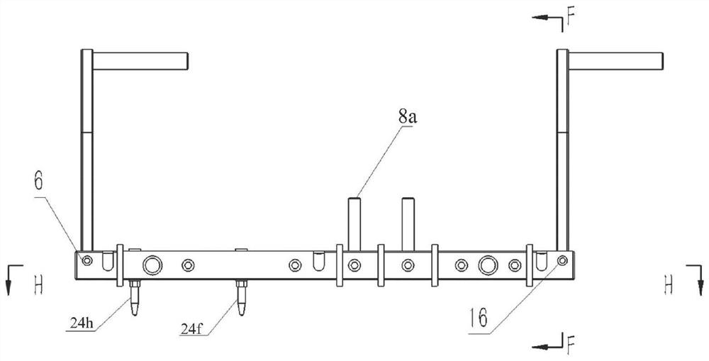
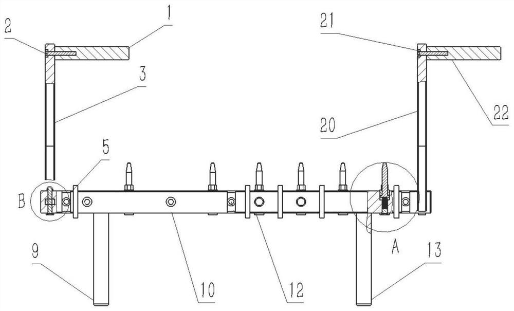
[0034] The invention provides a mechanical emergency control device for a hydraulic lifting system on an emergency rescue vehicle, such as Figure 1 to Figure 6As shown, it includes a first cantilever 3, a second cantilever 20, a connecting substrate and multiple sets of striker assemblies. The upper ends of the first cantilever 3 and the second cantilever 20 are respectively provided with a first hinge shaft 1 and a second hinge shaft 22, and The first cantilever 3 and the first hinge shaft 1 are fixedly connected by the first screw 2, the second cantilever 20 and the second hinge shaft 22 are fixedly connected by the second screw 21, and the first hinge shaft 1 and the second hinge shaft 22 are in the same direction Arrangement, the lower ends of the first canti...


PUM


Abstract

The invention relates to a mechanical emergency control device for a hydraulic lifting system on an emergency rescue vehicle, which comprises a first cantilever, a second cantilever, a connecting base plate and multiple sets of striker assemblies, the first cantilever and the second cantilever are respectively arranged in The first end and the second end of the connection base plate are connected, the connection base plate includes a first base plate, a second base plate, a third base plate and a fourth base plate, and a plurality of handles are arranged on the connection base plate, and between the first base plate and the second base plate, Between the second substrate and the third substrate and before the third substrate and the fourth substrate are rotatably connected, and a plurality of sets of striker assemblies are respectively arranged on the second substrate and the third substrate. In the present invention, multiple groups of striker assemblies are arranged on the connection base plate, and different striker assemblies are combined through the operating handle, thereby controlling the electromagnetic switch of the electro-hydraulic control cabinet on the emergency rescue vehicle, which is beneficial to realize hydraulic lifting on the emergency rescue vehicle The functions of lifting, loading, handling, braking and emergency stop of the system.

Description

technical field [0001] The invention belongs to the technical field of mechanical emergency control devices, and in particular relates to a mechanical emergency control device for a hydraulic lifting system on an emergency rescue vehicle. Background technique [0002] The hydraulic lifting system of emergency rescue vehicles mostly adopts manipulation control or panel integrated control. In daily application, the number of switches of the hydraulic lifting system on emergency rescue vehicles is large. When the above functions are realized, multiple staff members are required to cooperate with the operation, and the work is difficult and difficult. It has a high rate of misoperation, and solves problems such as operating system failures that may occur when rescue vehicles are operating at the construction site. In order to further meet the support of the hydraulic lifting system on the emergency rescue vehicle or the construction needs of on-board lifting, loading, handling, ...

Claims


Application Information

Patent Timeline
Patent Type & Authority Patents(China)
IPC IPC(8): B66C13/56B66C13/42
CPCB66C13/56B66C13/42
Inventor 巩明德赵东华赵丁选陈圣光常金明李晓明贾冠永于志伟
Owner YANSHAN UNIV
Learn More