
Magnetorheological polishing device and method and polished workpiece

A magnetorheological polishing and driving device technology, which is applied in the direction of grinding/polishing safety devices, grinding/polishing equipment, surface polishing machine tools, etc., and can solve problems such as unfavorable magnetorheological polishing device polishing

Pending Publication Date: 2022-02-15
SOUTH UNIVERSITY OF SCIENCE AND TECHNOLOGY OF CHINA
View PDF0 Cites 1 Cited by
  • Summary
  • Abstract
  • Description
  • Claims
  • Application Information

AI Technical Summary

Problems solved by technology

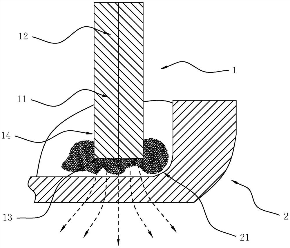
refer to figure 1 , shows a schematic diagram of the liquid-carrying head of the current magnetorheological polishing device. As shown in the figure, the magnetic field of the magnetorheological polishing device is usually provided by a magnet. One pole of the magnet faces the workpiece to be processed, and the other pole of the magnet away from the workpiece to be processed, at this time the magnetic field lines of the magnet are as figure 1 As shown by the dotted line in , the magnetic particles and abrasive particles in the polishing liquid are concentrated in the center of the bottom surface of the carrier head, while the side of the carrier head and the junction area between the bottom surface and the side surface lack a sufficient number of magnetic particles with sufficient adsorption force and abrasive particles, which is not conducive to the polishing of the inner concave surface of the workpiece by the magnetorheological polishing device

Method used


Image

  • Magnetorheological polishing device and method and polished workpiece
  • Magnetorheological polishing device and method and polished workpiece
  • Magnetorheological polishing device and method and polished workpiece

Examples


Embodiment Construction

[0026] This part will describe the specific embodiment of the present invention in detail, and the preferred embodiment of the present invention is shown in the accompanying drawings, and the function of the accompanying drawings is to supplement the description of the text part of the specification with figures, so that the present invention can be intuitively and vividly understood Each technical feature and the overall technical solution, but it should not be construed as a limitation on the protection scope of the present invention.

[0027] In the description of the present invention, if it involves orientation description, for example, the orientation or positional relationship indicated by "upper", "lower", "front", "back", "left", "right" etc. is based on the The orientation or positional relationship is only for the convenience of describing the present invention and simplifying the description, but does not indicate or imply that the device or element referred to must...


PUM

PropertyMeasurementUnit
surface roughnessaaaaaaaaaa

Abstract

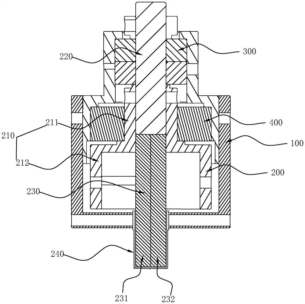
The invention relates to the technical field of precision machining. The invention discloses a magnetorheological polishing device and method and a polished workpiece. According to one scheme, the magnetorheological polishing device comprises a rack, a liquid carrying head and a first driving device, wherein the first driving device is used for driving the liquid carrying head to rotate; the liquid carrying head comprises a first magnetic pole and a second magnetic pole which are opposite in polarity; and the first magnetic pole and the second magnetic pole are distributed in a radial direction of the liquid carrying head. According to the magnetorheological polishing device, by arranging the first magnetic pole and the second magnetic pole which are distributed in the radial direction of the liquid carrying head, magnetic particles and abrasive particles in polishing liquid can be concentrated on a side face and a joint area of the bottom face and the side face of the liquid carrying head, and enough adsorption force can be kept for the abrasive particles on the side face and the joint area of the bottom face and the side face of the liquid carrying head in a grinding process, so that polishing of an inner concave face of a workpiece is achieved.

Description

technical field [0001] The invention relates to the technical field of precision machining, in particular to a magnetorheological polishing device, a polishing method and a polished workpiece. Background technique [0002] The basic principle of the magnetorheological polishing process is: the polishing fluid exhibits low-viscosity Newtonian fluid characteristics when no magnetic field is applied, and will produce magnetorheological effects when subjected to a certain intensity of magnetic field, showing high viscosity and low fluidity The Bingham body characteristics, showing the Bingham body characteristics of the polishing liquid and the relative movement between the product, in order to achieve the purpose of removing the surface material of the product. refer to figure 1 , shows a schematic diagram of the liquid-carrying head of the current magnetorheological polishing device. As shown in the figure, the magnetic field of the magnetorheological polishing device is usua...

Claims


Application Information

Patent Timeline
Patent Type & Authority Applications(China)
IPC IPC(8): B24B1/00B24B29/02B24B41/02B24B41/00B24B55/00
CPCB24B1/005B24B29/02B24B41/02B24B41/00B24B55/00
Inventor 吴勇波乔先鹏陈威王富全
Owner SOUTH UNIVERSITY OF SCIENCE AND TECHNOLOGY OF CHINA
Learn More