
Cascade hydropower station coupling risk dynamic identification method

An identification method and technology of hydropower stations, applied in the field of risk identification of water conservancy and hydropower projects, can solve the problems of multiple risk coupling relationships and transmission routes of cascade hydropower stations are unclear, lacking, and the internal function relationship of a single risk of cascade hydropower stations is unclear, etc.

Pending Publication Date: 2022-02-11
CHINA INST OF WATER RESOURCES & HYDROPOWER RES
View PDF0 Cites 1 Cited by
  • Summary
  • Abstract
  • Description
  • Claims
  • Application Information

AI Technical Summary

Problems solved by technology

[0002] The joint operation and dispatch of cascade hydropower stations involves many aspects of flood control, power generation, water supply, shipping, and ecology. It is a complex multi-dimensional nonlinear system. Influenced by many uncertain factors such as human improper operation, there are inevitably many potential risks, which will affect the safe operation of cascade hydropower station groups, as well as the full play of flood control, power generation, water supply, shipping, and ecological comprehensive functions and benefits
[0003] At present, the risk identification and control of large cascade hydropower stations have the following deficiencies: the lack of a systematic and comprehensive method for identifying the complex risks of hydropower stations; the internal role of a single risk in cascade hydropower stations is not clear; the coupling relationship and transmission routes of multiple risks in cascade hydropower stations are not clear. Clear; it is difficult to dynamically evaluate the dynamic changes of potential risk events in cascade hydropower stations under the risk relationship of multiple complex coupling and interweaving

Method used


Image

  • Cascade hydropower station coupling risk dynamic identification method
  • Cascade hydropower station coupling risk dynamic identification method
  • Cascade hydropower station coupling risk dynamic identification method

Examples


specific Embodiment 2

[0091] Step 1. Risk identification

[0092] (1) First, according to the aforementioned Table 1, conduct a risk survey on the common risks of cascade hydropower stations in a certain river basin, and the results of the survey are shown in Table 1-1. A total of 12 risk events are listed, and the influence of deformation bodies in the evaluation unit of the dam in the reservoir area on the safety of the reservoir area, dam, and generator sets is taken as an example to illustrate in detail.

[0093] Table 1-1 Common risk survey of cascade hydropower stations in a certain river basin

[0094]

[0095]

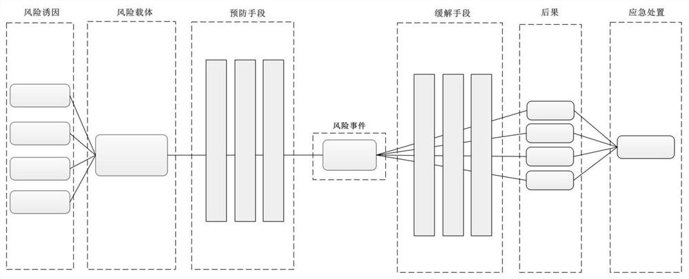
[0096] (2) Further, according to the census results in Table 1-1, use figure 1 The bow-tie diagram shown in the diagram draws the risk bow-tie diagram of the influence of deformable bodies on the safety of the reservoir area, dam, and unit, and intuitively shows the internal risk transmission relationship, such as Figure 6 shown.

[0097] (3) Further, according to the afor...


PUM


Abstract

The invention provides a cascade hydropower station coupling risk dynamic identification method, and the method comprises the steps: dividing risk evaluation units according to important regions of interest and functions of a risk-affected hydropower station hub; performing risk census and identification work according to the risk division unit to obtain a risk identification result; according to the risk identification result, adopting a causal chain method, sorting out coupling relations among multiple risk events, and drawing multiple risk coupling topological graphs; establishing a risk ledger of the cascade hydropower station according to the risk coupling topological graph and the risk identification result; calculating a risk event coupling failure probability dynamic state according to the risk ledger; and dynamically establishing a risk real-time evaluation system according to the risk event coupling failure probability. And evaluating the dynamic risk level of each potential risk event in real time according to the result of the risk coupling failure probability dynamic calculation.

Description

technical field [0001] The invention relates to the field of risk identification of water conservancy and hydropower projects, in particular to a method for dynamically identifying coupling risks of cascade hydropower stations. Background technique [0002] The joint operation and dispatch of cascade hydropower stations involves many aspects of flood control, power generation, water supply, shipping, and ecology. It is a complex multi-dimensional nonlinear system. Influenced by many uncertain factors such as human improper operation, there are inevitably many potential risks, which will affect the safe operation of cascade hydropower station groups, as well as the comprehensive functions and benefits of flood control, power generation, water supply, shipping, and ecology. [0003] At present, the risk identification and control of large cascade hydropower stations have the following deficiencies: the lack of a systematic and comprehensive method for identifying the complex r...

Claims


Application Information

Patent Timeline
IPC IPC(8): G06Q10/06G06Q50/06
CPCG06Q10/0635G06Q50/06
Inventor 林俊强刘毅汤正阳任玉峰曹光荣彭期冬张迪李岩桃朱博然李海枫尚毅梓
Owner CHINA INST OF WATER RESOURCES & HYDROPOWER RES
Learn More