
Method for monitoring aging degree of transformer insulating oil

A transformer insulating oil, aging degree technology, applied in the direction of instruments, measuring devices, scientific instruments, etc., to avoid equipment accidents, ensure operation safety, and reduce major losses

Pending Publication Date: 2022-02-08
ELECTRIC POWER RES INST OF STATE GRID ANHUI ELECTRIC POWER +2
View PDF1 Cites 1 Cited by
  • Summary
  • Abstract
  • Description
  • Claims
  • Application Information

AI Technical Summary

Problems solved by technology

[0004] The technical problem to be solved by the present invention is that the monitoring method for the aging degree of transformer insulating oil in the prior art cannot be used for on-line monitoring and data transmission of the quality change of transformer insulating oil

Method used


Image

  • Method for monitoring aging degree of transformer insulating oil
  • Method for monitoring aging degree of transformer insulating oil
  • Method for monitoring aging degree of transformer insulating oil

Examples


Embodiment 1

[0032] The monitoring method for the aging degree of transformer insulating oil includes the following steps:

[0033] (1) Acquisition of working samples of transformer insulating oil

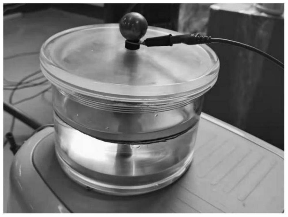
[0034] Using the same batch of transformer insulating oil samples as the substrate, continuous surface discharge experiments are carried out on the discharge device. The test discharge device is shown as figure 1 As shown, the experimental device is an existing device with a cavity volume of about 3L. The purpose of placing double layers of insulating paper is to avoid breakdown of insulating oil.

[0035] (1) The series resonance test device is used as a booster device, and the existing pulse current method is used as a partial discharge measurement method. Circuit principle such as figure 2 shown. The present invention can also use other methods in the prior art to perform partial discharge on the insulating oil, thereby simulating the natural lightning strikes that the insulating oil re...

Embodiment 2

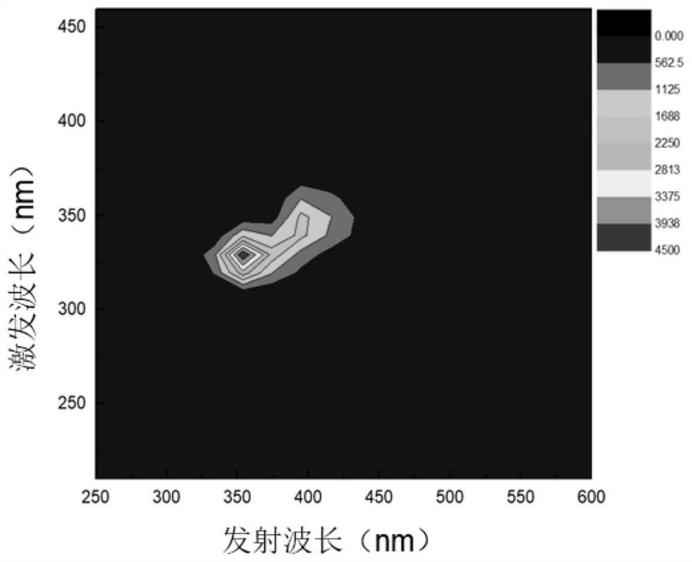
[0065] For verifying the sensitivity of the inventive method, adopt step (3) in embodiment 1 to detect following actual oil sample to be tested, measurement result is as follows Figure 5 and shown in Table 1.

[0066] Table 1 Test results

[0067] batch number Sample name Fluorescence intensity (a.u.) 1 Fresh oil without shock 5526 2 Oil samples artificially simulated for a period of time by electric shock 3527 3 Oil samples that have been in operation for ten years 268.4

[0068] In the table, 1 represents the new oil that has not undergone electric shock, 2 represents the oil sample that artificially simulates the natural electric shock for a period of time, and 3 represents the oil sample that has actually been operated for ten years.

[0069] From the above examples and results, it can be known that the present invention is easy to operate, high in sensitivity, small in sample size, and can obtain data on the aging degree of insulat...


PUM


Abstract

The invention discloses a method for monitoring the aging degree of transformer insulating oil, and relates to the technical field of transformer aging degree monitoring of power equipment. The method comprises the following steps of: (1) measuring the three-dimensional fluorescence of transformer insulating oil with different aging degrees, and constructing a transformer insulating oil aging degree model; and (2) taking the transformer insulating oil, measuring three-dimensional fluorescence to obtain fluorescence intensity data, and judging the aging degree of the transformer insulating oil according to the transformer insulating oil aging degree model in the step (1). According to the method, whether equipment has fault hidden danger information or not can be predicted through early and real-time diagnosis results, so that the insulation performance state of the transformer insulating oil is effectively monitored, the real-time performance of detection is improved, equipment accidents are avoided, heavy loss is reduced, the reliability of equipment operation is improved, and finally, the operation safety of a power system is ensured.

Description

technical field [0001] The invention relates to the technical field of monitoring the aging degree of transformers of power equipment devices, in particular to a method for monitoring the aging degree of transformer insulating oil. Background technique [0002] Transformer is one of the most important equipment in the power transmission link, and transformer insulating oil is one of the most important insulating materials for transformers; it not only plays the role of insulation, but also has the functions of heat dissipation and arc extinguishing. During the long-term operation of high-voltage lines, the insulating oil will be affected by various external factors such as oxygen, humidity, high temperature, ultraviolet rays, strong electric fields and impurities, and its mechanical and electrical properties will gradually age, which will easily cause heating at the cable terminal and even insulation shock Therefore, it is necessary to study and analyze the aging characteris...

Claims


Application Information

Patent Timeline
IPC IPC(8): G01N21/64G01N21/01
CPCG01N21/64G01N21/01
Inventor 赵跃宋玉梅马凤翔董王朝徐芳刘伟刘子恩赵恒阳谢佳冷威李坤鹏
Owner ELECTRIC POWER RES INST OF STATE GRID ANHUI ELECTRIC POWER
Learn More