
Calculation method for grounding resistance of horizontally laid disc grounding body

A technology of grounding resistance and calculation method, applied in the field of high-voltage power transmission and transformation, can solve the problems of inability to reduce and calculate grounding resistance, and achieve the effects of reducing grounding costs, lightning accidents, casualties and equipment losses

Pending Publication Date: 2022-02-01
CHENGDU TECHCAL UNIV
View PDF0 Cites 0 Cited by
  • Summary
  • Abstract
  • Description
  • Claims
  • Application Information

AI Technical Summary

Problems solved by technology

[0005] The purpose of the present invention is: the present invention provides a method for calculating the grounding resistance of a horizontally laid disc grounding body, which solves the problem that the grounding resistance cannot meet the design requirements due to the high soil resistivity in the area where the current transmission line is located. Technical aspects of resistance reduction and calculation

Method used


Image

  • Calculation method for grounding resistance of horizontally laid disc grounding body
  • Calculation method for grounding resistance of horizontally laid disc grounding body
  • Calculation method for grounding resistance of horizontally laid disc grounding body

Examples


Embodiment 1

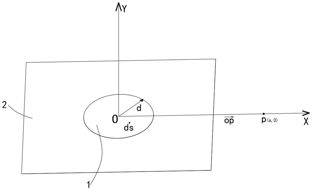
[0034] Such as figure 1 As shown, this embodiment provides a calculation device for the grounding resistance of a horizontally laid disc grounding body, including a disc 1, which is grounded and shaped as a circular panel. The size of the circular panel is based on the local installation and geological conditions. After calculating the conditions, it is found that the disc 1 is placed on the level ground 2 or embedded in the ground 2 . For protection and safety, placing the disc 1 on the level ground 2 is also related to local installation and geological conditions.

Embodiment 2

[0036] Based on the calculation device for the grounding resistance of a horizontally laid disc grounding body provided above, this embodiment also discloses a calculation method for the grounding resistance d (disc resistance) of a plane circular structure in a high soil resistivity area, including the following step:

[0037] Step 1): Place a uniformly charged disc with resistance on the level ground, and the electric potential at any point on the plane outside the disc is as follows:

(1)

[0038]

[0039] is the charge density of the uniformly charged disk;

[0040] x=rcosθ0≤r≤d

[0041] y=rsinθ0≤θ≤2π

[0042]

[0043] Among them, with the center O of the disc as the origin, any point p on the horizontal ground outside the disc, Establish a Cartesian coordinate system p(a, 0) for the x-axis, make a microelement ds (ds diameter → 0) on the disk, ds center point coordinates ds (x, y), ds = dxdy, microelement ds on the disk An electric potential is generated at ...


PUM


Abstract

The invention discloses a calculation method for the grounding resistance of a horizontally laid disc grounding body, and belongs to the technical field of high-voltage power transmission and transformation. The problems that the grounding resistance is difficult to meet the design requirement and cannot be reduced and calculated due to high resistivity of soil in regions where power transmission lines of power plants and transformer substations are located are solved. The grounding device comprises a disc; the grounding disc is a circular panel, and the disc is placed on the horizontal ground; the potential of the disc at any point on the horizontal ground can be accurately calculated through a calculation formula; according to the invention, the grounding disc is transited to the soil current density to reduce the grounding resistance, the grounding resistance value of a disc panel adopted in a high soil resistivity area can be specifically calculated, the accurate calculation of the grounding resistance of the disc is realized, and the calculation problem of the grounding resistance of a grounding grid is solved.

Description

technical field [0001] The invention relates to the technical field of high-voltage power transmission and transformation, in particular to a method for calculating the grounding resistance of a horizontally laid disc grounding body. Background technique [0002] In terms of lightning current impact grounding, most of the transmission lines in my country are in minefields. Lightning accidents are the main component of power grid accidents, which greatly affect the safe operation and stability of the power grid. Reducing grounding resistance is the main factor to improve the lightning resistance level of transmission lines. methods and measures. [0003] There is no mature calculation method for the composite grounding grid, and it is often to increase the buried amount of the grounding body, so that there is no way to calculate the mutual shielding between the grounding bodies. The regulations stipulate that in areas with soil resistivity above 2000Ω·m, the grounding body sho...

Claims


Application Information

Patent Timeline
Patent Type & Authority Applications(China)
IPC IPC(8): G06F17/10
CPCG06F17/10Y02E60/00
Inventor 张晓东张艳丽冯明陈宇峰于文萍唐静吴婕萍
Owner CHENGDU TECHCAL UNIV
Learn More