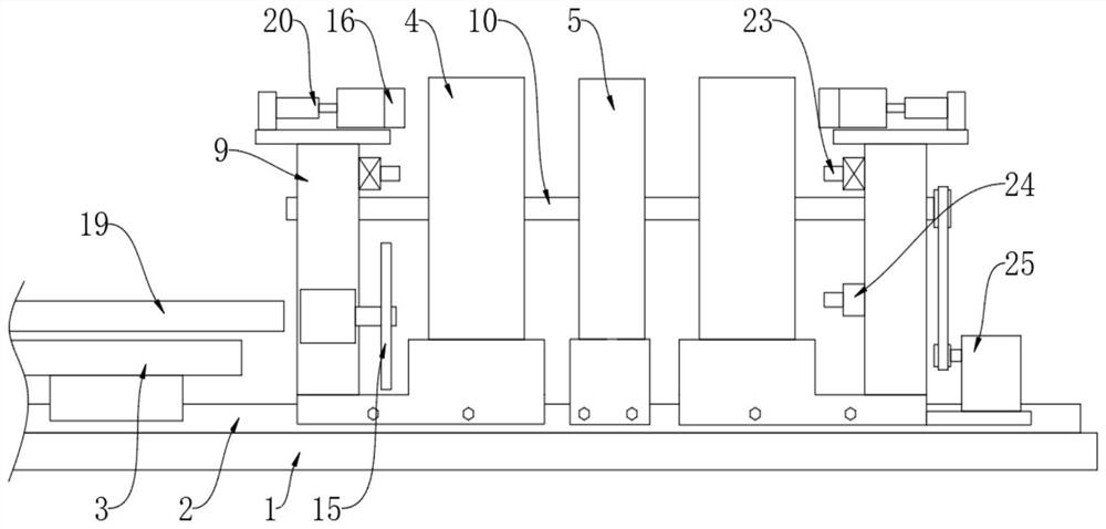
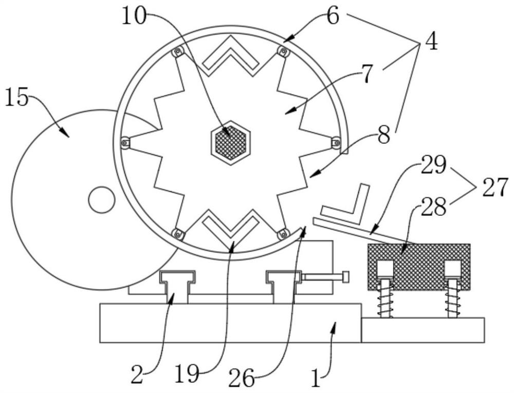
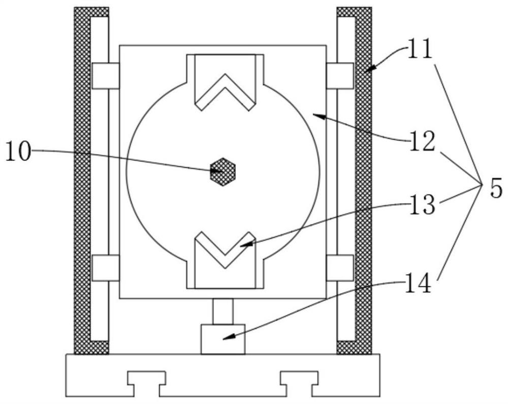
A cutting system for transmission tower production

A technology of cutting system and transmission tower, which is applied in manufacturing tools, other manufacturing equipment/tools, metal processing, etc. It can solve the problems of improper installation, overhead, warping of cutting edges, etc., and achieves improved work efficiency, convenient use, and convenient cutting Effect

Active Publication Date: 2022-08-02
QINGDAO WUXIAO GRP
View PDF8 Cites 1 Cited by
  • Summary
  • Abstract
  • Description
  • Claims
  • Application Information

AI Technical Summary

Problems solved by technology

[0004] The cutting method adopted in the above technical solution is likely to cause warped edges, unevenness, or cutting burrs. When welding or installing the tower body, it is easy to form overhead and the installation is not in place. Therefore, grinding and chamfering and straightening are required separately. Reshaping adds an additional process. Based on this, this application proposes a cutting system for the production of transmission towers to solve the above problems

Method used


Image

  • A cutting system for transmission tower production
  • A cutting system for transmission tower production
  • A cutting system for transmission tower production

Examples


Embodiment Construction

[0029] The technical solutions in the embodiments of the present invention will be clearly and completely described below with reference to the accompanying drawings in the embodiments of the present invention. Obviously, the described embodiments are only a part of the embodiments of the present invention, but not all of the embodiments.

[0030] In the description of the present invention, it should be understood that the terms "upper", "lower", "front", "rear", "left", "right", "top", "bottom", "inside", " The orientation or positional relationship indicated by "outside" is based on the orientation or positional relationship shown in the accompanying drawings, and is only for the convenience of describing the present invention and simplifying the description, rather than indicating or implying that the indicated device or element must have a specific orientation, so as to The specific orientation configuration and operation are therefore not to be construed as limitations of...


PUM


Abstract

The invention discloses a cutting system for power transmission tower production, comprising a base plate, the upper surface of the base plate is provided with a sliding rail, and the surface of the sliding rail is respectively slidably installed with a feeding table, a material turning frame and a material limiting frame. There are two turning frames, which are symmetrically arranged on the left and right sides of the material limiting frame. The material turning frame includes a sliding seat, the upper surface of the sliding seat is fixedly connected with a limiting ring, and a rotating disk is rotatably connected in the limiting ring. The surface of the disc is provided with a V-shaped groove. In this cutting system, by setting the material limit frame and the material turning frame, the angle steel is inserted into the two material turning frames, and the material limit frame can be used to implement the pressing and fixing of the angle steel, and the saw disc cutting machine cuts the angle steel, along with the material. The rotation of the flip frame, the cut angle steel rises, the chamferer chamfers both ends, removes burrs, cuts the angle steel, and then performs chamfering and shaping, which is completed at one time, thereby achieving the effect of improving work efficiency and making it more convenient to use. .

Description

technical field [0001] The invention relates to the technical field of transmission tower production, in particular to a cutting system for transmission tower production. Background technique [0002] Transmission line towers are mainly composed of three parts: tower head, tower body and tower legs. Their structural characteristics are that various tower types are space truss structures, and the rods are mainly composed of single equilateral angle steel or combined angle steel. Rough bolts are used for inter-connection, and the bolts are connected by shear force. Individual components are welded to form an assembly. The tower body uses the most angle steel. Cutting the angle steel in the production process is also a lot of work. [0003] Chinese patent CN113458841A discloses a cutting system for angle steel production of power transmission towers, including a shearing machine and a mounting table, the mounting table is provided with a mounting groove running through its widt...

Claims


Application Information

Patent Timeline
Patent Type & Authority Patents(China)
IPC IPC(8): B23P23/04B23Q7/00
CPCB23P23/04B23Q7/00
Inventor 韩华
Owner QINGDAO WUXIAO GRP
Why Eureka
Try Eureka