
Oblique 45-degree mirror optical scanning device for laser radar

A technology of optical scanning and laser radar, which is applied in the direction of measuring devices, using re-radiation, re-radiation of electromagnetic waves, etc., can solve the problems that the technology is difficult to achieve, unfavorable for large-scale scanning, and the small field of view of polygonal mirror scanning. The effect of detection distance

Inactive Publication Date: 2022-01-28
四川吉埃智能科技有限公司
View PDF11 Cites 0 Cited by
  • Summary
  • Abstract
  • Description
  • Claims
  • Application Information

AI Technical Summary

Problems solved by technology

Common reflective mirrors in the reflective scanning system include polygonal mirrors and elliptical mirrors (oblique 45° mirrors). Polygonal mirrors have a small scanning field of view, which is not conducive to large-scale scanning
The design of the optical scanning device needs to consider issues such as the system field of view, scanning speed, aperture, angle measurement requirements, and rotational balance, which are difficult to achieve with existing technologies.

Method used


Image

  • Oblique 45-degree mirror optical scanning device for laser radar
  • Oblique 45-degree mirror optical scanning device for laser radar
  • Oblique 45-degree mirror optical scanning device for laser radar

Examples


Embodiment Construction

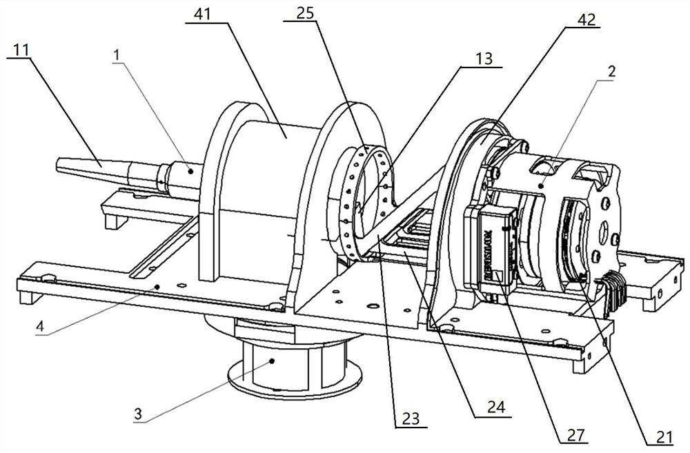
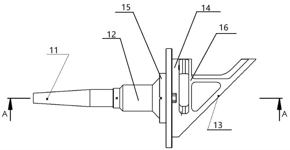
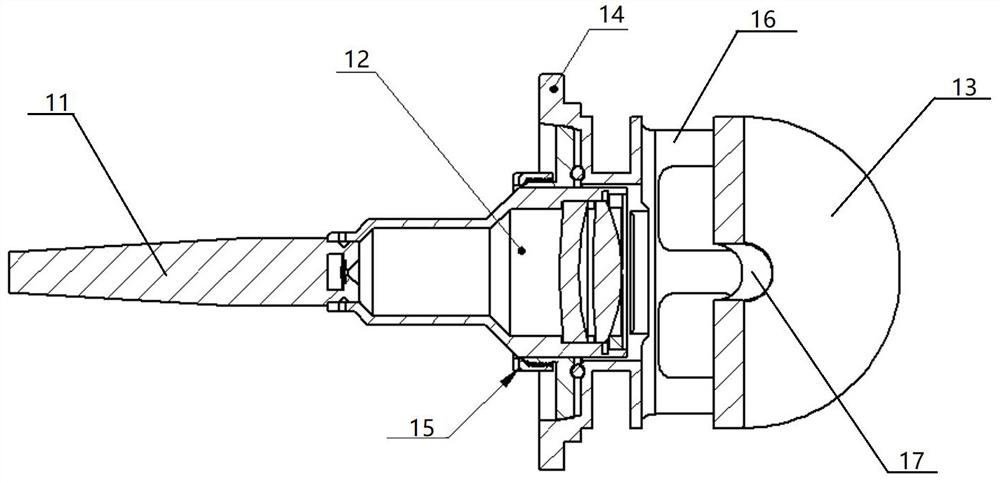
[0029] In order to enable those skilled in the art to better understand the technical solutions of the present invention, the present invention will be further described in detail below in conjunction with specific embodiments.

[0030] Such as Figure 1-Figure 7 As shown, the present invention includes a laser emitting unit 1 for exciting laser light, a laser receiving unit 3 for receiving reflected laser light 102, and a rotating scanning unit 2 for deflecting emitted laser light 101 to form a scanning section. In addition, a frame 4 is included, and the frame 4 includes a bottom plate 43, on which the exit mounting mechanism 41 for fixedly installing the laser emitting unit 1 and the rotating scanning unit for fixedly installing are coaxially installed on the bottom plate 43 in sequence from front to back. 2 of the rotating installation mechanism 42; the outgoing installation mechanism 41 is cylindrical, and its bottom and the corresponding position of the bottom plate 43 a...


PUM


Abstract

The invention discloses an oblique 45-degree mirror optical scanning device for a laser radar. The device comprises a laser emitting unit for exciting laser, a laser receiving unit for receiving reflected laser, and a rotary scanning unit for deflecting the emitted laser to form a scanning section; and the rotary scanning unit comprises a scanning mirror forming an angle of 45 degrees with emergent laser excited by the laser emitting unit, and a driving device for driving the scanning mirror to rotate. The principle of the invention lies in that the driving device is utilized to drive the scanning mirror to rotate, so that the emergent laser is reflected to different angles to form a larger scanning section.

Description

technical field [0001] The invention relates to an optical scanning device applied to laser radar. Background technique [0002] Lidar is a radar system that emits laser beams to detect characteristic quantities such as the position and speed of targets. Its working principle is to send a detection signal (laser beam) to the target, and then compare the received signal (target echo) reflected from the target with the transmitted signal, and after proper processing, the relevant information of the target can be obtained, such as Target distance, azimuth, height, speed, attitude, and even shape parameters, so as to detect, track and identify aircraft, missiles and other targets. It consists of a laser transmitter, an optical receiver, a turntable and an information processing system. The laser converts electrical pulses into optical pulses and emits them. The optical receiver then restores the optical pulses reflected from the target into electrical pulses and sends them to t...

Claims


Application Information

Patent Timeline
Patent Type & Authority Applications(China)
IPC IPC(8): G01S17/02G01S7/481
CPCG01S17/02G01S7/4817
Inventor 黄陆君虞静唐海龙黄贵余
Owner 四川吉埃智能科技有限公司
Learn More