Device for testing ductility strength of new energy material

A new energy material and strength testing technology, applied in the direction of testing the ductility of materials, measuring devices, analyzing materials, etc., can solve problems such as damage and injury of new energy materials by force

Pending Publication Date: 2022-01-28
张玲慧
View PDF0 Cites 0 Cited by
  • Summary
  • Abstract
  • Description
  • Claims
  • Application Information

AI Technical Summary

Problems solved by technology

[0003] However, in the existing technology, in the ductility test of new energy materials, people need to manually pull the new energy materials for testing. In this process, people may use too much force to cause damage to the new energy materials. Requires people to manually unload, which can lead to injury during testing

Method used


Image

  • Device for testing ductility strength of new energy material
  • Device for testing ductility strength of new energy material
  • Device for testing ductility strength of new energy material

Examples


Embodiment 1

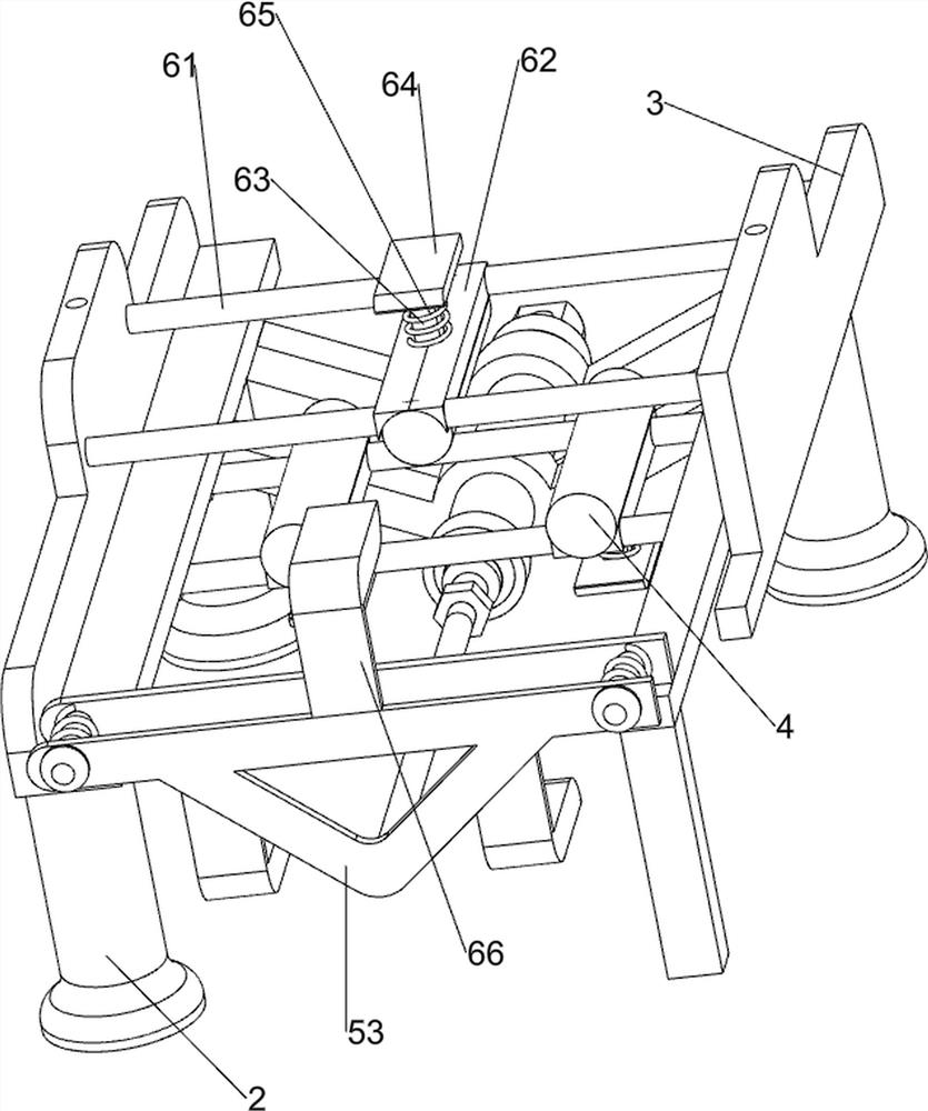
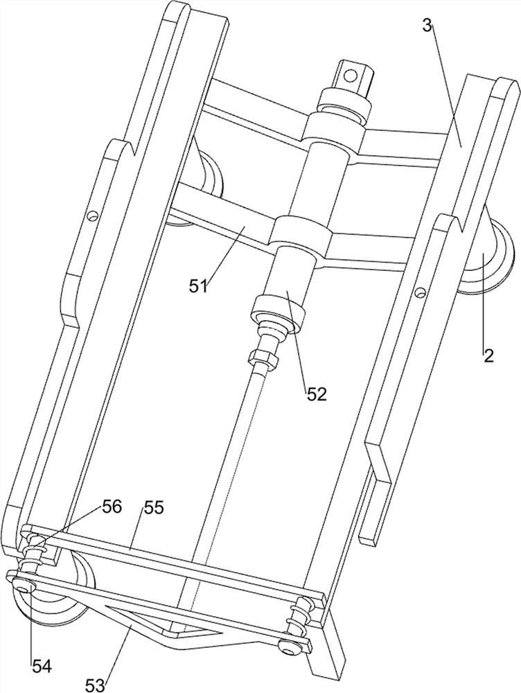
[0027] A ductility strength test device for new energy materials, such as figure 1 , figure 2 and image 3 As shown, it includes a base 1, a supporting column 2, a guide rail 3, a pressing column 4, a pushing mechanism 5 and a pressing mechanism 6. The top of the base 1 is provided with three supporting columns 2 evenly spaced, and the two supporting columns 2 on the rear side The guide rail 3 is arranged on the supporting column 2 between and the front side, and the pressing mechanism 6 is provided with three pressing columns 4. The sliding type is provided with a pushing mechanism 5 between the left side of the guide rail 3, and a pushing mechanism 5 is provided between the guide rail 3 tops. Press-down mechanism 6 is arranged.

[0028] Pushing mechanism 5 comprises mounting seat 51, cylinder 52, push plate 53, first guide rod 54, bonding rod 55 and first spring 56, guide rail 3 bottom right sides are symmetrically provided with mounting seat 51, between mounting seat 51 ...

Embodiment 2

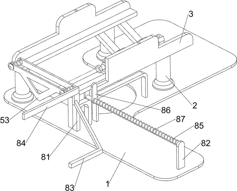
[0032] On the basis of Example 1, such as Figure 4 , Figure 5 , Figure 6 and Figure 7As shown, it also includes a blanking assembly 7. The blanking assembly 7 includes a support 71, a slide rail 72, a feed frame 73 and a push rod 74. Slide rail 72 is arranged, and slide rail 72 is all connected with guide rail 3, and slide rail 72 top is provided with feeding frame 73, and slide rail 72 is provided with push rod 74 slidingly.

[0033] Also includes a push assembly 8, the push assembly 8 includes a support frame 81, a stopper 82, an engaging rod 83, an oblique rod 84, a third guide rod 85, a push block 86 and a third spring 87, and the middle of the left side of the top of the base 1 There is a support frame 81, a stopper 82 is provided on the left front side of the top of the base 1, an oblique bar 84 is provided on the front side of the push plate 53, an engaging rod 83 is provided on the front side of the oblique bar 84, and a third guide rod 85 is provided on the rea...


PUM


Abstract

The invention relates to a testing device and particularly relates to a ductility strength testing device for a new energy material. A technical problem to be solved is to provide the ductility strength testing device for the new energy material, which can be used for automatic extrusion testing and automatic blanking. The ductility strength testing device for the new energy material comprises a base and three supporting columns, wherein the three supporting columns are evenly arranged at the top of the base at intervals; guide rails are arranged between the two supporting columns on one side and on the supporting columns on one side; the three downward pressing columns are arranged on a downward pressing mechanism; and a pushing mechanism is arranged between one sides of the guide rails in a sliding manner. According to the new energy material extrusion device, a bonding block is driven by a special-shaped block to move inwards, the bonding block drives a second guide rod to move towards the inner side, the second guide rod can drive a downward pressing column to move towards the inner side, new energy materials can be extruded when the downward pressing column moves towards the inner side, and the effect of automatic extrusion is achieved.

Description

technical field [0001] The invention relates to a testing device, in particular to a ductility strength testing device for new energy materials. Background technique [0002] New energy materials mainly include: superconducting materials, solar cell materials, hydrogen storage materials, etc. It is a new scientific and technological concept for the economical utilization of non-renewable resources that was triggered after the introduction of the concept of environmental protection. It refers to newly developed or It is some super-performance materials under research and development. [0003] However, in the existing technology, in the ductility test of new energy materials, people need to manually pull the new energy materials for testing. In this process, people may use too much force to cause damage to the new energy materials. Humans are required to unload manually, which can lead to injuries during testing. [0004] In view of the above-mentioned problems in the prior ...

Claims


Application Information

Patent Timeline
Patent Type & Authority Applications(China)
IPC IPC(8): G01N3/28G01N3/02G01N3/04B65G47/82
CPCG01N3/28G01N3/02G01N3/04B65G47/82G01N2203/0003G01N2203/0019G01N2203/0044
Inventor 张玲慧
Owner 张玲慧
Why Eureka
Try Eureka