
Municipal engineering drainage structure

A drainage structure and engineering technology, applied to drainage structures, water supply devices, waterway systems, etc., can solve the problems of underground pipeline blockage, road accumulation of water, easy to block drainage holes, etc., and achieve the effect of reducing blockage and road accumulation of water

Inactive Publication Date: 2022-01-28
福建省城川建设工程有限公司
View PDF1 Cites 0 Cited by
  • Summary
  • Abstract
  • Description
  • Claims
  • Application Information

AI Technical Summary

Problems solved by technology

[0004] In the process of realizing the present application, the inventor found that there are at least the following problems in this technology: when it rains, the rainwater will wash away the garbage on the ground towards the inspection well, and then the rainwater will enter the inspection well from the drain hole, and the garbage will remain on the well cover. Sometimes large garbage such as plastic bags can easily block the drainage holes, resulting in water accumulation on the road. If large garbage such as plastic bags are discharged into the inspection well, it may cause blockage of underground pipes, which will also cause water accumulation on the road surface.

Method used


Image

  • Municipal engineering drainage structure
  • Municipal engineering drainage structure
  • Municipal engineering drainage structure

Examples


Embodiment Construction

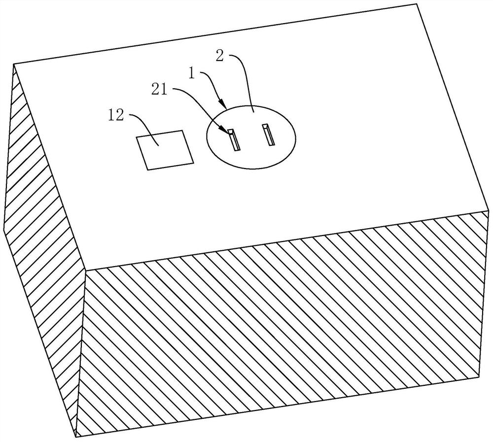
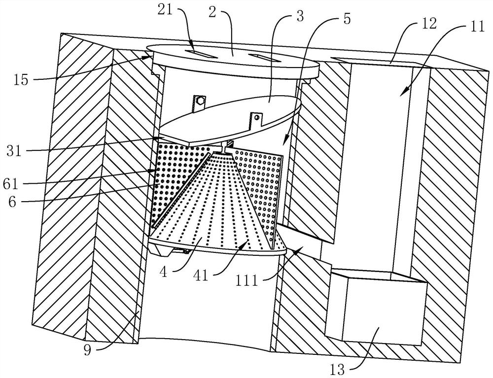
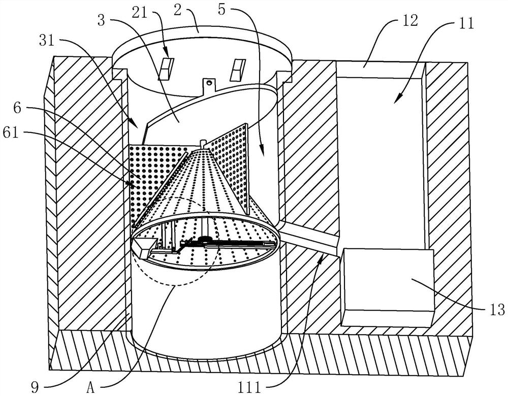
[0035] The following is attached Figure 1-4 The application is described in further detail.

[0036] The embodiment of the application discloses a municipal engineering drainage structure. see figure 1 and figure 2 , The municipal engineering drainage structure includes the well body 1 and the well cover 2 of the inspection well. During construction, the well body 1 is set on the ground and extends downwards. The wellhead is in a circular shape and is provided with an overlapping groove 15. The well cover 2 is covered in the overlapping groove 15. The well cover 2 is provided with a water inlet 21 for supplying rainwater and Garbage enters the well body 1.

[0037] see figure 2, the well body 1 is provided with an installation sleeve 9, and the outer peripheral side of the installation sleeve 9 is in sliding contact with the inner wall of the well body 1 up and down. The outer peripheral side of the top of the installation sleeve 9 is fixed with an annular lap strip, ...


PUM


Abstract

The invention discloses a municipal engineering drainage structure, and relates to the technical field of municipal engineering, the municipal engineering drainage structure comprises a well body of an inspection well and a well lid covering a well mouth of the well body, a water inlet is formed in the well lid, a guide plate is obliquely arranged on the well body, and a falling opening allowing rainwater and garbage to fall down is formed in the side, away from the well lid, of the guide plate, the well body is provided with a filter plate, a plurality of filter holes are evenly formed in the filter plate at intervals, the filter plate is obliquely arranged and extends along the circumferential track, one side of the bottom of the filter plate makes contact with the well wall, one side of the top of the filter plate is away from the well wall, a filter cavity is formed between the filter plate and the well wall, and a plurality of push plates are evenly arranged between the filter plate and the well wall at intervals, the well body is provided with a driving assembly, a collecting groove upwards penetrating out of the well body is formed in the peripheral side hole wall of the well body, the well body is provided with a communicating opening, a cover plate used for covering a top groove opening of the collecting groove is arranged at the top of the well body, and a collecting frame used for collecting garbage is arranged in the collecting groove. The possibility of pavement water accumulation can be reduced.

Description

technical field [0001] The application relates to the technical field of municipal engineering, in particular to a municipal engineering drainage structure. Background technique [0002] Drainage system is a major part of municipal engineering, among which the inspection well is the most common, used to connect the drainage structure of the ground and underground drainage pipe network, and the wellhead part of the inspection well is usually covered with a inspection well cover, which can reduce pedestrians falling into Possibility of manhole. [0003] At present, the Chinese utility model patent whose notification number is CN205894112U discloses a kind of magnetic inspection well cover, comprising: a well cover and a wellhead inner sleeve. The well cover is installed on the inner casing of the wellhead, the inner casing of the wellhead is installed on the wellhead, the inner casing of the wellhead is provided with a step, the step and the side wall of the step are provided...

Claims


Application Information

Patent Timeline
Patent Type & Authority Applications(China)
IPC IPC(8): E03F5/04E03F5/06E03F5/14E03F7/00B01D29/11B01D29/64B01D29/94
CPCE03F5/0401E03F5/06E03F5/0404E03F5/041E03F7/00B01D29/114B01D29/6415B01D29/94
Inventor 吴桂春雷斌斌周建镇高平平
Owner 福建省城川建设工程有限公司
Learn More