


Quick Research
Generate reliable direction feasibility study reports for your R&D in just a few steps.

Technical Q&A
Discover and master advanced knowledge NOW. Basics, ideas, possibilities, all at once.

Find Solutions
As an expert in R&D theories, this can generate solutions to your technical problems instantly.

Evaluate Feasibility
Analyze your overall solution with one click, know your potential R&D risks in advance.

Monitor Landscape
Get weekly tech updates, stay abreast of the latest tech innovations and key insights.
A non-ferrous metal forging drawing device
A technology for non-ferrous metals and forgings, which is applied in the field of non-ferrous metal forging drawing devices, which can solve the problems of high labor intensity and restrictions on the specifications of non-ferrous metal forgings, and achieve the effect of avoiding scratches and scratches
- Summary
- Abstract
- Description
- Claims
- Application Information
AI Technical Summary
Problems solved by technology
Method used
Image


Examples
Embodiment 1
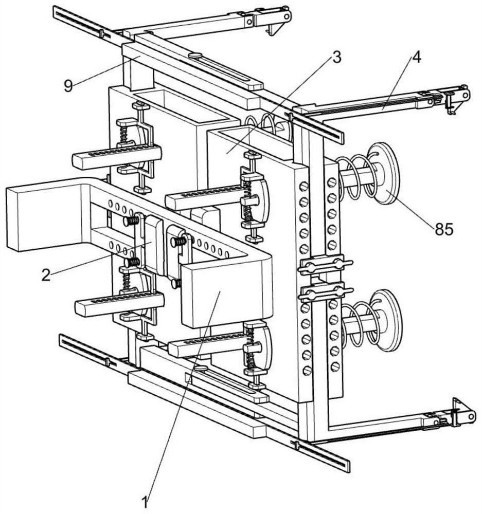
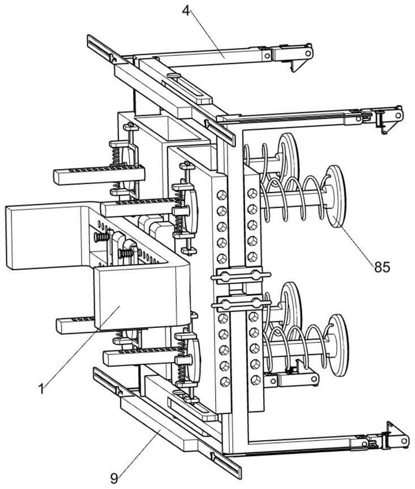
[0039] A non-ferrous metal forging drawing device, such as figure 1 , figure 2 , image 3 , Figure 4 , Figure 5 , Image 6 , Figure 7 , Figure 8 , Figure 9 , Figure 10 , Figure 11 As shown, it includes an external connector 1, a fixed sliding seat 2, a fixed guide plate 3, a lifting L-shaped plate 4, a width adjusting assembly 5, a lifting adjusting assembly 6 and a flipping assembly 7. The external connecting member 1 is slidably connected with two The fixed sliding seat 2 is fixed on the fixed sliding seat 2 with a fixed guide plate 3, and the fixed guide plate 3 is symmetrically slidably connected with a lifting L-shaped plate 4, the width adjustment component 5 is arranged on the side of the fixed sliding seat 2, and the width adjustment component 5 is used In order to adjust the width distance of the lifting L-shaped plate 4, a lifting adjustment assembly 6 is provided on one side of the lifting L-shaped plate 4. The lifting adjustment assembly 6 is used ...
Embodiment 2
[0047] On the basis of Example 1, as Figure 11 , Figure 12 As shown, it also includes a forging middle support assembly 8, the fixed guide plate 3 is provided with a forging middle support assembly 8, the forging middle support assembly 8 is used to support non-ferrous metal forgings, and the forging middle support assembly 8 includes a current regulator 81, The movable lower pressure rod 82, the squeeze spring 83, the adjustment rod 84, the slotted support round seat 85, the compression spring 86, the fixed electromagnet seat 87, the special-shaped clamping rod 88 and the tension spring two 89, the movable flip plate 72 is fixedly connected on one side There is a current regulator 81, the current regulator 81 is used for outputting current, a movable pressing rod 82 is slidably connected to the current regulator 81, and a compression spring 83 is connected between the movable pressing rod 82 and the current regulator 81, and the movable pressing rod 82 is connected to the c...
Embodiment 3
[0050] On the basis of Example 2, as figure 2 , image 3 As shown, a connecting pull plate 9 is also included. The two moving support guide rods 73 at the same level are jointly slidably connected with the connecting pull plate 9 . The connecting pull plate 9 facilitates the staff to directly pull the two moving support guide rods 73 .
[0051] The staff can directly pull the connecting pull plate 9, and the connecting pull plate 9 will simultaneously drive the two moving support guide rods 73 to move away from the non-ferrous metal forging, saving the trouble of pulling the moving support guide rods 73 one by one.
PUM
 Abstract
Description
Claims
Application Information
 - R&D Engineer
- R&D Manager
- IP Professional
- Industry Leading Data Capabilities
- Powerful AI technology
- Patent DNA Extraction
Browse by: Latest US Patents, China's latest patents, Technical Efficacy Thesaurus, Application Domain, Technology Topic, Popular Technical Reports.
© 2024 PatSnap. All rights reserved.Legal|Privacy policy|Modern Slavery Act Transparency Statement|Sitemap|About US| Contact US: help@patsnap.com