Reinforcing and fixing structure for rotating shaft of flap-type rudder of ship

A fixed structure, flap rudder technology, applied in the field of ship flap rudder, can solve problems such as falling off, performance degradation, aileron and main wing rotation problems, etc., to avoid corrosion, small strength loss, and effectively fix the hinge shaft.

Pending Publication Date: 2022-01-28
SHANGHAI MERCHANT SHIP DESIGN & RES INST
View PDF0 Cites 0 Cited by
  • Summary
  • Abstract
  • Description
  • Claims
  • Application Information

AI Technical Summary

Problems solved by technology

[0003] Due to the frequent rotation between the aileron and the main wing of the flap rudder, the requirements for the hinge axis 1 are very high, and the strength of the hinge axis 1 is required to be better, and the rotation is flexible. The exposed end of 1 is installed with a sealing plate 3, and then the sealing plate 3 and the hinge shaft 1 are fixed by bolts 2, thereby limiting the rotation of the hinge shaft
[0004] The disadvantage of the prior art is that when the main wing and aileron of the flap rudder are installed, a circle of bolts 2 needs to be used to fix them, and the space here is narrow, which makes the installation inconvenient. They are all directly submerged in seawater, which is easy to corrode and rust, which makes it inconvenient to operate in the later disassembly and maintenance. At the same time, the performance of the bolt 2 will be reduced after corrosion, and there will be a risk of falling off, which will cause problems with the rotation of the aileron and the main wing, and even produce ailerons. risk of shedding

Method used


Image

  • Reinforcing and fixing structure for rotating shaft of flap-type rudder of ship
  • Reinforcing and fixing structure for rotating shaft of flap-type rudder of ship
  • Reinforcing and fixing structure for rotating shaft of flap-type rudder of ship

Examples


Embodiment Construction

[0020] In the following description, numerous specific details are given in order to provide a more thorough understanding of the present invention. It will be apparent, however, to one skilled in the art that the present invention may be practiced without one or more of these details. In other examples, some technical features known in the art are not described in order to avoid confusion with the present invention.

[0021] In order to thoroughly understand the present invention, detailed steps and detailed structures will be provided in the following description, so as to illustrate the technical solution of the present invention. Preferred embodiments of the present invention are described in detail below, however, the present invention may have other embodiments besides these detailed descriptions.

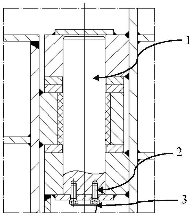
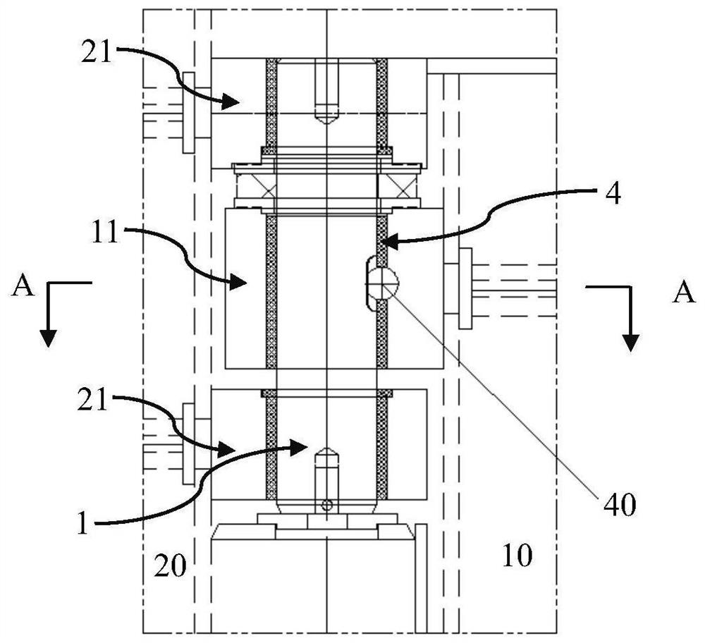
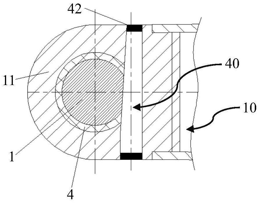
[0022] refer to Figure 2-6 As shown, the present invention provides a strengthening and fixing structure for the rotating shaft of the ship's flap rudder. The flap rudder ...


PUM


Abstract

The invention provides a reinforcing and fixing structure for a rotating shaft of a flap-type rudder of a ship. Notches with the same height are formed in a hinge shaft penetrating through a main wing lug plate and a lining, and the bottom surface of the notch of the hinge shaft is an inclined surface; and at least one conical through hole is formed in the main wing lug plate in the thickness direction in a penetrating mode, a wedge-shaped lock pin which transversely penetrates through the hinge shaft and the opening of the lining at the same time is arranged in each conical through hole, and the wedge-shaped lock pins make close contact with the inner walls of the conical through holes and the inclined face of the hinge shaft. Waterproof mechanisms are arranged at the two ends of the conical through hole to seal the conical through hole. The wedge-shaped lock pin penetrates through the main wing lug plate, the lining and the hinge shaft from the side face, the effect of effectively fixing the hinge shaft can be achieved, meanwhile, the strength loss of the hinge shaft is minimum when the wedge-shaped lock pin penetrates through the middle relative to the position, and due to the fact that the hinge shaft only needs to be provided with a small notch and is sealed through epoxy resin, corrosion of the fixing pin shaft is avoided.

Description

technical field [0001] The invention relates to a flap rudder of a ship, in particular to a strengthening and fixing structure for a rotating shaft of a ship flap rudder. Background technique [0002] Flap rudder is to make the rudder blade into two parts, the main wing and the aileron. When the main wing rotates an angle α, the aileron follows the main wing and at the same time rotates with the help of the transmission device, so as to turn another angle β relative to the main wing, thereby improving the rudder effect . [0003] Due to the frequent rotation between the aileron and the main wing of the flap rudder, the requirements for the hinge axis 1 are very high, and the strength of the hinge axis 1 is required to be better, and the rotation is flexible. The exposed end of 1 is equipped with a sealing plate 3, and then the sealing plate 3 and the hinge shaft 1 are fixed by bolts 2, thereby limiting the rotation of the hinge shaft. [0004] The disadvantage of the prior...

Claims


Application Information

Patent Timeline
IPC IPC(8): B63H25/38
CPCB63H25/381B63H25/382B63H2025/387
Inventor 沈立宁黎峰李健刘浩宇朱冬健顾峰
Owner SHANGHAI MERCHANT SHIP DESIGN & RES INST
Why Eureka
Try Eureka