
Robot two-degree-of-freedom ankle joint structure module

A technology of structural modules and ankle joints, applied in the field of humanoid robots, can solve problems such as high motor torque requirements, low center of gravity of robot legs, complex ankle joint structure, etc., to achieve balance and stability, simple structure, and low manufacturing cost Effect

Pending Publication Date: 2022-01-28
BEIJING GANGTIEXIA TECH CO LTD
View PDF7 Cites 1 Cited by
  • Summary
  • Abstract
  • Description
  • Claims
  • Application Information

AI Technical Summary

Problems solved by technology

[0004] In view of the deficiencies in the prior art mentioned above, the first object of the present invention is to propose a robot two-degree-of-freedom ankle joint structure module, which solves the problem of the complex structure of the ankle joint of the existing humanoid robot and the high requirement for motor torque, and the relatively high center of gravity of the robot's legs. low problem

Method used


Image

  • Robot two-degree-of-freedom ankle joint structure module
  • Robot two-degree-of-freedom ankle joint structure module
  • Robot two-degree-of-freedom ankle joint structure module

Examples


Embodiment 1

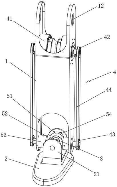
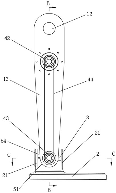
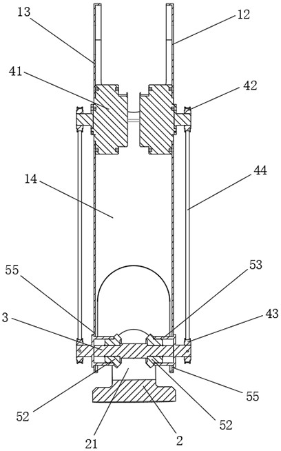
[0037] Embodiment 1, combining Figure 1 to Figure 8 , a robot two-degree-of-freedom ankle joint structure module, including a calf arm 1, a foot 2, a cross connecting shaft 3, a gear assembly and a driving device 4, the foot 2 is arranged under the calf arm 1 through the cross connecting shaft 3, and the cross The longitudinal axis portion of the connecting shaft 3 is rotationally connected with the foot 2 .

[0038] The calf arm 1 is a square tube structure with open upper and lower ends, which includes two long side plates 13 arranged opposite to each other, and the middle parts of the front and rear sides of the two long side plates are fixedly connected by a connecting plate 14 Integrate to form a square tubular calf arm 1, and the calf arm 1 adopts a hollow structure, which is beneficial to reduce its own weight and install components inside it.

[0039] Two knee joint shaft holes 12 are provided symmetrically on the left and right sides of the upper end of the calf arm...

Embodiment 2

[0050] Example 2, combined with Figure 1 to Figure 8 , the working method of the two-degree-of-freedom ankle joint structure module of the above-mentioned robot roughly includes the following steps:

[0051] Step 1: The thigh arm drives the calf arm to move upwards. When the foot leaves the ground, the two servo motors 41 receive instructions from the robot control system to start and determine the rotation direction of the output end of the servo motors 41 .

[0052] Step 2, the servo motor 41 respectively drives the two bevel gears 52 to rotate synchronously, and the rotation direction is opposite, the two bevel gears 52 drive the bevel gear 1 51 to rotate around its axis, and drive the cross connecting shaft 3 to partially rotate around its longitudinal axis After the foot 2 rotates to a predetermined angle around the longitudinal axis of the cross connecting shaft 3, the two bevel gears 2 52 stop rotating, and the foot 2 keeps the left and right inclination angle unchange...


PUM


Abstract

The invention discloses a robot two-degree-of-freedom ankle joint structure module, which comprises a shank arm, a foot, a cross connecting shaft, a gear assembly and driving devices, the foot is arranged below the shank arm through the cross connecting shaft, and the longitudinal shaft part of the cross connecting shaft is rotationally connected with the foot. The gear assembly comprises a first bevel gear arranged on the longitudinal shaft part of the cross-shaped connecting shaft and two second bevel gears symmetrically arranged on the two sides of the lower end of the shank arm, the two second bevel gears are both in running fit with the shank arm, and the first bevel gear is meshed with the two second bevel gears. The two driving devices are symmetrically arranged on the two sides of the shank arm, the lower end of each driving device is connected with the second bevel gear on the same side, and the driving devices drive the two second bevel gears to rotate synchronously. A servo motor controls the rotation mode of the cross connecting shaft through the transmission mechanism and the bevel gear assembly, rotation of the foot around the transverse axis part or the longitudinal axis part of the cross connecting shaft is achieved, the posture of the foot is adjusted, the structure is simpler, the gravity center position is improved, and gait balance control is more stable.

Description

technical field [0001] The invention relates to the technical field of humanoid robots, in particular to a robot two-degree-of-freedom ankle joint structure module. Background technique [0002] With the rapid development of science and technology, people pay more and more attention to the development and application of humanoid robots. Humanoid robots have many joints, and generally each joint has a motor for drive control, but the performance requirements and overall layout of the motors are different for each joint of a humanoid robot. Usually, in order to facilitate the gait motion control of the robot, the center of gravity of the robot will generally be raised as much as possible. [0003] At present, the main problems existing in the prior art are: 1. The two degrees of freedom of the ankle joint of the humanoid robot are generally controlled by two driving motors separately, and the joint rotation has high performance requirements on the torque of a single motor, an...

Claims


Application Information

Patent Timeline
Patent Type & Authority Applications(China)
IPC IPC(8): B62D57/032
CPCB62D57/032
Inventor 陈天祥张锐
Owner BEIJING GANGTIEXIA TECH CO LTD
Learn More