Eureka AIR delivers breakthrough ideas for toughest innovation challenges, trusted by R&D personnel around the world.

Device for detecting active escape behavior of animal

An animal detection and active technology, which is applied in animal repellents, animal houses, visible signal devices, etc. Strengthen the warning degree and reduce the effect of friction

Active Publication Date: 2022-01-28
HUNAN UNIV OF CHINESE MEDICINE
View PDF9 Cites 0 Cited by
  • Summary
  • Abstract
  • Description
  • Claims
  • Application Information

AI Technical Summary

Problems solved by technology

[0004] The purpose of the present invention is to solve the problem that staff often need to stand around the device in the prior art to observe the evasion behavior of the detected animals. Because in the above method, the staff is standing around the device, it is easy to make the detected animal A device for detecting the active avoidance behavior of animals is proposed due to the uncertainty of the animal's active avoidance behavior caused by the influence of the staff

Method used


Image

  • Device for detecting active escape behavior of animal
  • Device for detecting active escape behavior of animal
  • Device for detecting active escape behavior of animal

Examples


Embodiment 1

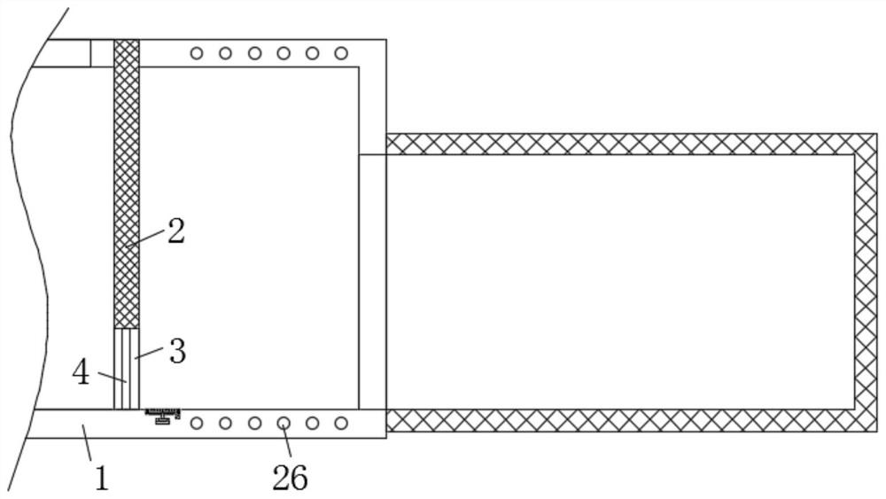
[0029] refer to Figure 1-6 , a device for detecting active evasion behavior of animals, comprising a peripheral cage 1, a central cage 2 is fixedly installed in the middle of the peripheral cage 1, an opening 3 is opened on the lower side of the central cage 2, and a door is installed at the opening 3 Body 4, the inner bottom end of the outer cage 1 corresponds to the opening 3 with a pedal 5, the middle part of the lower end of the pedal 5 is fixedly equipped with a connecting rod-6, the connecting rod-6 is covered with a spring-7, and the lower end of the connecting rod-6 The limiting plate 8 is fixedly installed, and the pedal 5 and the connecting rod 6 are slidably connected to the peripheral cage 1. The inner bottom of the peripheral cage 1 is fixedly installed with a switch 9 corresponding to the limiting plate 8, and the pedal 5 is provided with an anti-retreat The cone plate 10, the anti-retraction cone plate 10 runs through the upper end of the step plate 5;

[0030...

Embodiment 2

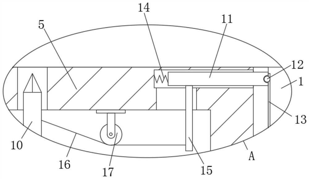
[0032] refer to Figure 1-6 , in this embodiment, it is basically the same as Embodiment 1. What is more optimal is that the left and right ends of the pedal 5 are plugged and slidably connected with anti-seam side plates 11, and the ends of the anti-seam side plates 11 that are far away from each other are all connected to the periphery. The inner wall of the cage 1 fits together, and the ends of the anti-seam side plates 11 that are far away from each other are provided with balls 12, and the balls 12 are connected to the anti-seam side plates 11 by rotation. One end is provided with a chute 13, and the ball 12 is rollingly connected to the outer cage 1. The ends of the anti-seam side plates 11 that are close to each other are fixedly installed with a spring 2 14, and the ends of the spring 2 14 that are close to each other are fixedly connected to the pedal 5. , the lower end of the anti-seam side plate 11 is fixedly equipped with a connecting rod two 15, and the connecting...

Embodiment 3

[0035] refer to Figure 1-6, in this embodiment, it is basically the same as Embodiment 1. What is more optimal is that two connecting rods 20 are hinged symmetrically on the left and right sides of the upper end of the support plate 19, and the upper end of the connecting rod 20 is hinged with a slider 21. One end of the block 21 close to each other is fixedly equipped with a conductive sheet 22, and the left and right sides of the lower end of the pedal 5 correspond to the sliders 21 on both sides, and are provided with chute two 23, and the slider 21 is slidably connected to the pedal 5. The lower side of the support plate 19 is provided with an eccentric wheel 24, the right end of the eccentric wheel 24 is fixedly installed with a motor 25, the right end of the motor 25 is fixedly installed with the peripheral cage 1, and the switch 9 is electrically connected with the motor 25, and the outer side of the peripheral cage 1 is fixedly installed There are several warning lamp...


PUM


Abstract

A device for detecting active escape behavior of an animal is disclosed. The device comprises a peripheral cage, a central cage is fixedly installed in the middle of the interior of the peripheral cage, an opening is formed in the lower side of the central cage, a door body is rotationally installed at the opening, a pedal is arranged at the position, corresponding to the opening, of the bottom end of the interior of the peripheral cage, and a first connecting rod is fixedly installed in the middle of the lower end of the pedal; a first spring sleeves the first connecting rod, a limiting plate is fixedly mounted at the lower end of the first connecting rod, the pedal and the first connecting rod are slidably connected with the peripheral cage, a switch is fixedly mounted at the position, corresponding to the limiting plate, of the inner bottom of the peripheral cage, and an anti-retreating conical plate is arranged in the pedal and penetrates through the upper end of the pedal. When the device is in use, conducting strips on the two sides are intermittently attached and separated, continuous flickering of an alarm lamp is achieved, the warning degree of the alarm lamp is enhanced, and workers in the distance are reminded to rapidly recognize the animal escape behavior.

Description

technical field [0001] The invention relates to the technical field of detection devices, in particular to a device for detecting active escape behaviors of animals. Background technique [0002] After retrieval, the patent application number CN203912869U discloses a "device for detecting active evasion behavior of animals", including a peripheral cage; a central cage suitable for placing animals, and the central cage is arranged in the peripheral cage. The surrounding wall of the central cage is provided with an opening, and the opening is provided with a door body for opening or closing the opening; the extending cage is arranged on the surrounding wall of the peripheral cage and is connected with the inside of the peripheral cage. connected. [0003] However, in the above-mentioned device, the staff often need to stand around the device to observe the evasion behavior of the detected animal. Because in the above-mentioned method, the staff is standing around the device, ...

Claims


Application Information

Patent Timeline
Patent Type & Authority Applications(China)
IPC IPC(8): A01K1/03A01M29/06G08B21/24G08B5/38
CPCA01K1/03A01M29/06G08B21/24G08B5/38Y02A40/70
Inventor 赵洪庆王宇红韩远山杨冬梅孟盼柳卓邹蔓姝
Owner HUNAN UNIV OF CHINESE MEDICINE
Why Eureka
Eureka Blog
Learn More