Keycap detection mechanism and detection method capable of effectively preventing pull hook of drawing block from being broken by collision

A detection mechanism and detection method technology, applied in the direction of applying stable tension/pressure to test the strength of materials, measuring devices, instruments, etc., can solve the problems of drawing block loss, damage, collapsed keycaps, etc., and reduce the detection cost , Improving detection efficiency and ensuring safety

Pending Publication Date: 2022-01-25
KUNSHAN HONGZHIXI AUTOMATION EQUIP
View PDF1 Cites 0 Cited by
  • Summary
  • Abstract
  • Description
  • Claims
  • Application Information

AI Technical Summary

Problems solved by technology

However, in practical applications, according to user feedback, it is found that the hooks on the drawing block are prone to breakage or damage, and the drawing block is seriously worn out.
[0004] After the applicant's analysis, the main reason for the crash of the hook is that there is an installation error in the installation of the drawing block. Every time the keycap is tested, there is actually a deviation between the actual position of the hook and the position of the hook identified in the system. And because the height gap between the keycap and the keyboard body is very small, a little installation error of the hook will easily cause the hook to collide with the keycap body and be damaged; in addition, because the keycap is not installed correctly, it is not supported by the elastic bracket. , leading to the appearance of collapsed keycaps, which are called "dead keys" in the industry. The existence of "dead keys" leads to insufficient gap between the keycaps and the keyboard body, so that the hooks are easy to hit the "dead key" body and crashed

Method used


Image

  • Keycap detection mechanism and detection method capable of effectively preventing pull hook of drawing block from being broken by collision
  • Keycap detection mechanism and detection method capable of effectively preventing pull hook of drawing block from being broken by collision
  • Keycap detection mechanism and detection method capable of effectively preventing pull hook of drawing block from being broken by collision

Examples


Embodiment 1

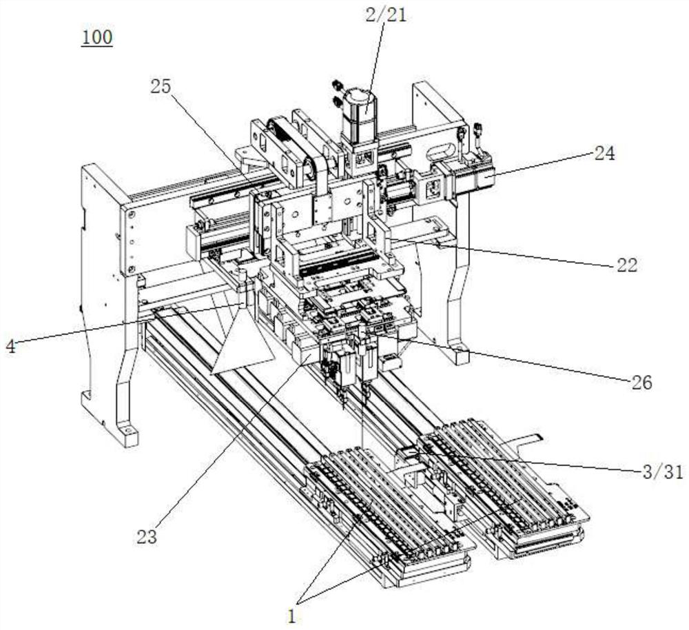
[0029] Please refer to Figure 1-Figure 4 , the present embodiment is a keycap detection mechanism 100 that can effectively avoid the pull hook of the drawing block from being broken. The test head module 2 and the visual detection module 3 for acquiring the position of each pull hook 234 .

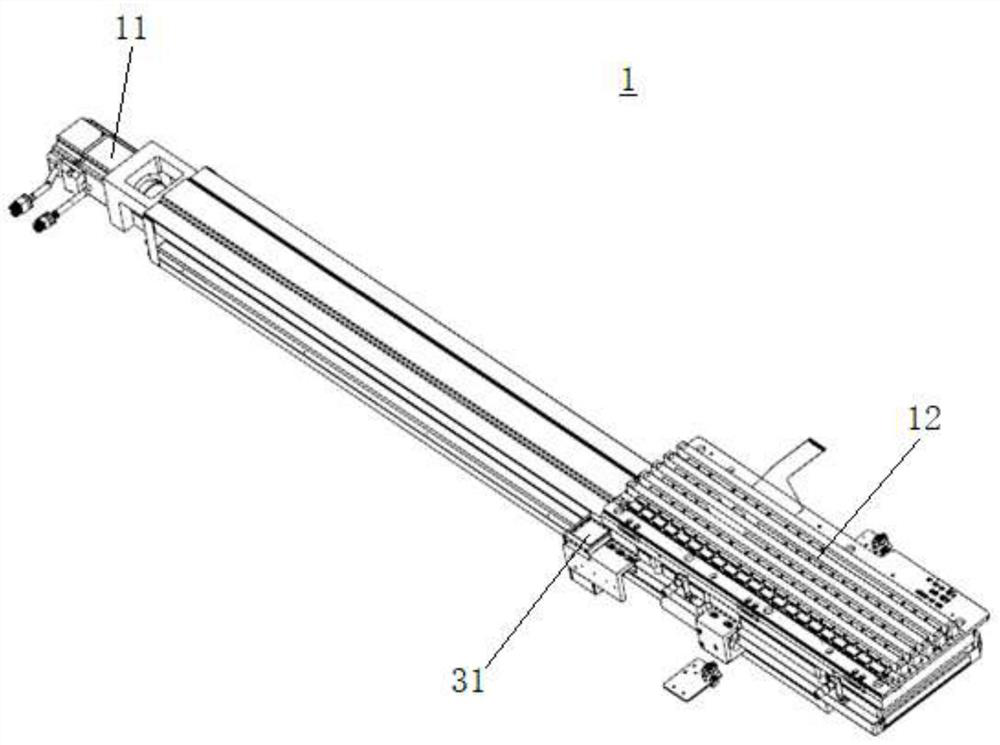
[0030] The keyboard loading and unloading conveying module 1 includes a Y-axis transfer mechanism 11 and a keyboard detection jig 12 driven by the Y-axis transfer mechanism 11 to move horizontally along the Y-axis.

[0031] The pull-out test head module 2 includes a Z-axis transfer mechanism 21 , a support frame 22 driven by the Z-axis transfer mechanism 21 to move up and down, and several test head assemblies 23 fixed on the support frame 22 .

[0032] The test head assembly 23 includes a first driving member 231, a pressure sensor 232 driven by the first driving member 231 to move up and down, a drawing block 233 arranged at the sensing end of the pressure sensor 232, and a drawing blo...


PUM


Abstract

The invention discloses a keycap detection mechanism and detection method capable of effectively preventing pull hooks of a pull block from being broken by collision. The keycap detection mechanism comprises a keyboard feeding and discharging conveying module, a pull test head module which is located above the keyboard feeding and discharging conveying module and comprises a plurality of pull hooks, and a visual detection module for obtaining the position of each pull hook. According to the invention, the position information of all the pull hooks is obtained by using a visual inspection technology, and a basis is provided for the adjustment of the positions of the pull hooks, so that the actual positions of the pull hooks before detection are consistent with the required position coordinates, thereby ensuring that the pull hooks can accurately extend into the gaps between the keycaps and the keyboard body during detection, and other keyboard components cannot be collided, so that the safety of the pull hooks is guaranteed, the phenomenon that the pull hooks are cracked up is effectively avoided, the detection efficiency is greatly improved, and the detection cost is reduced.

Description

【Technical field】 [0001] The invention belongs to the technical field of keyboard assembly equipment, and in particular relates to a keycap detection mechanism and a detection method that can effectively prevent the hook of a drawing block from being broken. 【Background technique】 [0002] Keyboards are generally assembled from aluminum substrates, circuit boards, scissor support frames, and keycaps. The main causes of poor elasticity or pull-out force of keyboard keycaps are currently known: 1) Bad incoming materials, such as aluminum substrates stuck Deformation of the hook, breakage of the central axis of the scissors support frame, or lack of material and collapse of the keycap structure where the inner and outer scissors are assembled, and defects in the four corners of the keycap and the fittings of the inner and outer scissors (that is, the written name is the water drop hole and the chute structure); 2) Poor assembly, such as damage to the keyboard or keycap structur...

Claims


Application Information

Patent Timeline
Patent Type & Authority Applications(China)
IPC IPC(8): G01N3/02G01N3/06G01N3/08
CPCG01N3/02G01N3/068G01N3/08
Inventor 刘利刚蒋海军
Owner KUNSHAN HONGZHIXI AUTOMATION EQUIP
Why Eureka
Try Eureka