Indicating grating of optical encoder

A technology of optical encoder and indicating grating, applied in the field of indicating grating of optical encoder, can solve problems such as difficulty in fully satisfying accuracy, imperfect light transmission area, etc.

Pending Publication Date: 2022-01-25
HIWIN MIKROSYST
View PDF0 Cites 0 Cited by
  • Summary
  • Abstract
  • Description
  • Claims
  • Application Information

AI Technical Summary

Problems solved by technology

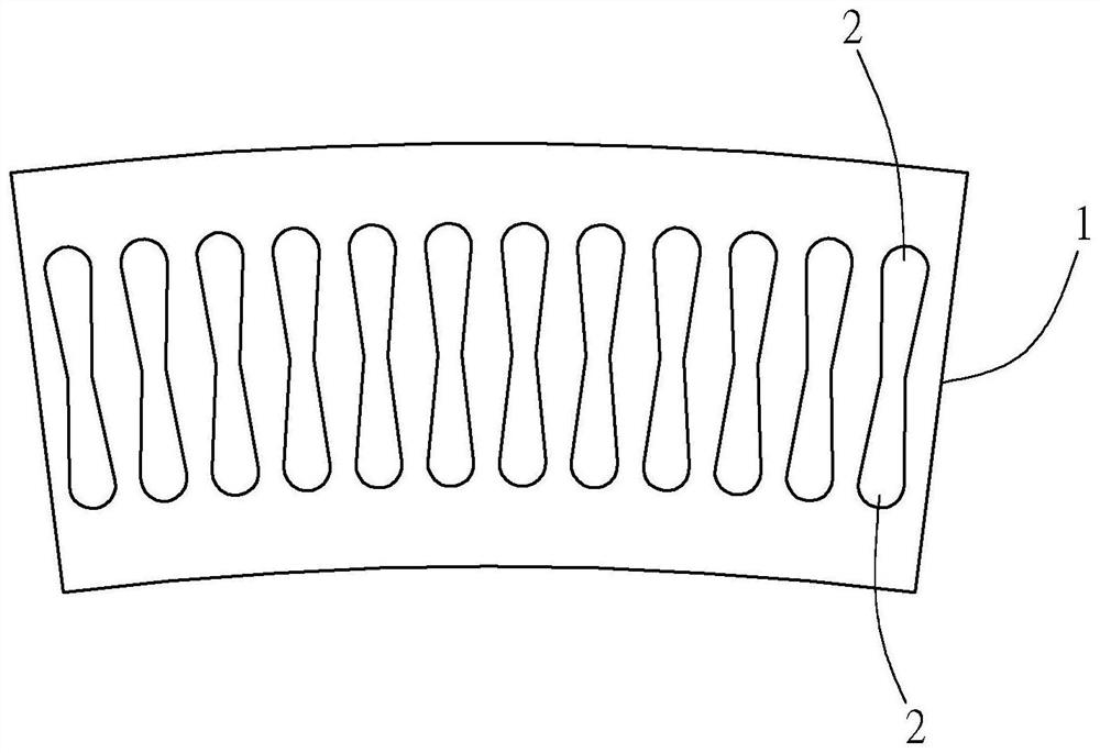
[0004] However, due to the increasing requirements of precision machinery for position analysis accuracy, such as figure 1 The known technology shown, because the technical content of the light-transmitting area (2) has not yet been perfected, the analytical precision, accuracy, and even the ability to avoid interference that it can provide have limitations, and it is difficult to completely Satisfies the precision required by precision machinery

Method used


Image

  • Indicating grating of optical encoder
  • Indicating grating of optical encoder
  • Indicating grating of optical encoder

Examples


Embodiment Construction

[0017] In order to make the purpose, technical solutions and advantages of the embodiments of the present invention clearer, the technical solutions in the embodiments of the present invention will be clearly and completely described below in conjunction with the drawings in the embodiments of the present invention. Obviously, the described embodiments It is a part of embodiments of the present invention, but not all embodiments. Based on the embodiments of the present invention, all other embodiments obtained by persons of ordinary skill in the art without making creative efforts belong to the protection scope of the present invention.

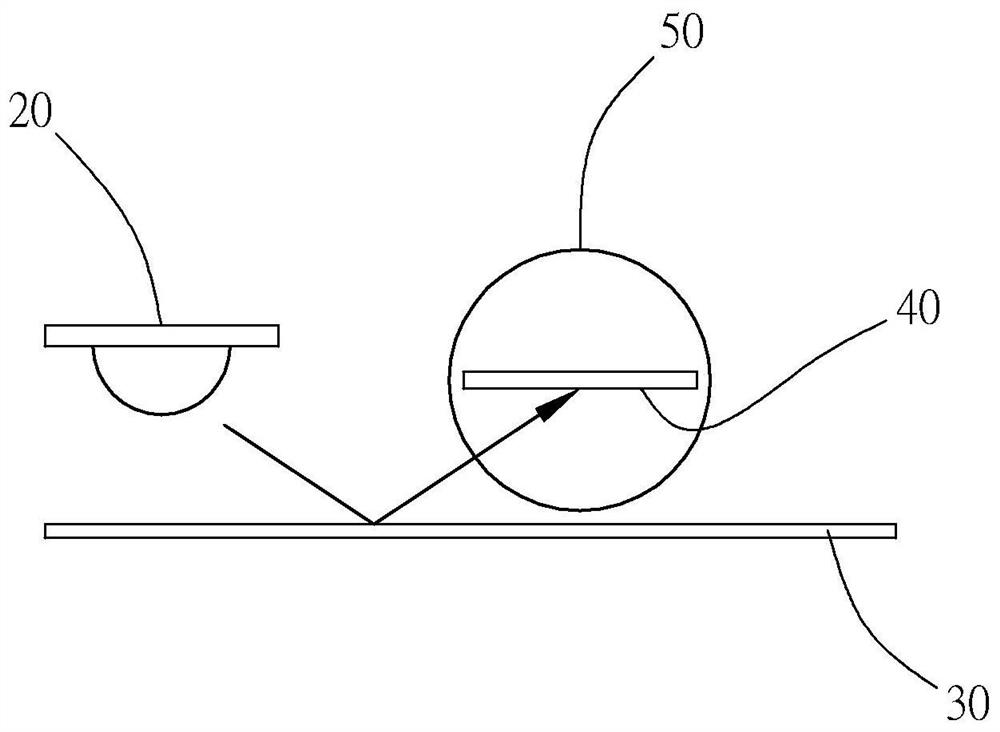
[0018] First, see Figure 2A , Figure 2B and image 3 As shown, the optical encoder (10) provided in a preferred embodiment of the present invention mainly includes a light source (20), a main grating (30), an index grating (40) and an optical sensor Ministry (50).

[0019] The principle of action of the optical encoder (10) and the rela...


PUM


Abstract

The indicating grating of the optical encoder provided by the invention has the main technical characteristics that the light-transmitting area proportion of the grating in unit area is improved, so that the utilization efficiency of a light source and the intensity of signals are increased, the light blocking proportion caused by foreign matters such as dust can be reduced, the influence degree of the foreign matters on the light intensity is reduced, the sensing precision of the optical encoder is improved.

Description

technical field [0001] The invention relates to position sensing technology, in particular to an index grating of an optical encoder. Background technique [0002] The encoder that analyzes the position with a sine wave signal uses a light sensor to receive different light intensity changes under the rotation of the code disc, and then obtains the current position through analysis. In order to produce an ideal sine wave, it reduces the required time for analysis. The calculation amount and the precise positioning of the application components are obtained. In the known technology, there is a method of changing the shape of the light receiving area, the shape of the light mask or the shape of the grating to obtain the ideal light intensity change when the code wheel rotates. result. [0003] see figure 1 The well-known indicator grating structure shown is that a plurality of light-transmitting areas (2) arranged in sequence and roughly in the shape of a figure 8 are arrange...

Claims


Application Information

Patent Timeline
Patent Type & Authority Applications(China)
IPC IPC(8): G01D5/347G01D5/38
CPCG01D5/347G01D5/38
Inventor 黄庭纬刘金松陈灿林
Owner HIWIN MIKROSYST
Why Eureka
Try Eureka