Stacking device for new energy automobile battery management

A new energy vehicle and battery management technology, applied in the direction of lifting devices, lifting frames, etc., can solve the problems of low device practicability, staff injury, new energy battery falling off, etc., to improve linkage and practicability, and increase clamping The effect of strength and overall structure is reasonable

Inactive Publication Date: 2022-01-25
杭州富阳锋拓机械有限公司
View PDF1 Cites 2 Cited by
  • Summary
  • Abstract
  • Description
  • Claims
  • Application Information

AI Technical Summary

Problems solved by technology

The above-mentioned patents have the following disadvantages: the device cannot protect the battery when the battery is raised, and when the clamping device is loose, the battery will fall off, causing damage to the battery, and may also cause injury to the staff, thereby causing life and property loss, and the battery cannot be rotated during lifting, resulting in low practicability of the device, complex structure, high manufacturing cost, and unsuitable for promotion
In addition, the above-mentioned patents are fixed by clamping from both sides when handling new energy batteries. This kind of clamping has disadvantages. If the clamping force is too large, it will cause damage to the new energy battery. The falling off of the new energy battery is even more dangerous. Therefore, there is an urgent need for a device that can stably hold the new energy battery without falling off during the handling process.

Method used


Image

  • Stacking device for new energy automobile battery management
  • Stacking device for new energy automobile battery management
  • Stacking device for new energy automobile battery management

Examples


Embodiment Construction

[0043] The technical solutions in the embodiments of the present invention will be clearly and completely described below in conjunction with the embodiments of the present invention. Apparently, the described embodiments are only some of the embodiments of the present invention, not all of them. Based on the embodiments of the present invention, all other embodiments obtained by persons of ordinary skill in the art without creative efforts fall within the protection scope of the present invention.

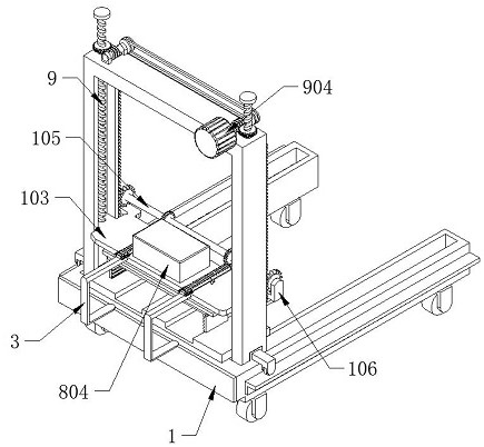
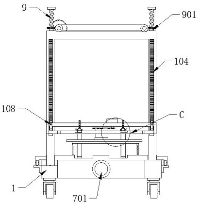
[0044] see Figure 1-11 As shown, a stacking device for new energy vehicle battery management includes a body 1, the top wall of the body 1 is provided with a first sliding groove 101, and also includes:

[0045] The displacement assembly is connected to the inside of the first sliding groove 101, and there are two displacement assemblies;

[0046] The sliding frame 102 is slidably connected to the outer wall of the displacement assembly, and the side wall of the sliding frame 10...


PUM


Abstract

The invention relates to the technical field of automobile batteries, in particular to a stacking device for new energy automobile battery management. The stacking device comprises a machine body with the top wall provided with first sliding grooves, and further comprises displacement assemblies connected to the interiors of the first sliding grooves; a sliding frame slidably connected to the outer walls of the displacement assemblies, wherein the side wall of the sliding frame is fixedly connected with first toothed plates which are symmetrically arranged; lifting assemblies connected to the top of the sliding frame, wherein the two lifting assemblies are symmetrically arranged, and the output ends of the lifting assemblies are connected with a lifting plate; a lifting motor connected to the side wall of the sliding frame; a protection device which is connected to the top of the lifting plate and comprises a driving assembly and a protection assembly, wherein the protection assembly is matched with a second sliding groove; a rotating assembly connected to the top wall of the lifting plate; and a clamping device connected to the output end of the rotating assembly. Potential safety hazards and property loss caused by falling of a battery in the lifting process can be avoided, the linkage and practicability of the device are improved, and the manufacturing cost of the device is reduced.

Description

technical field [0001] The invention relates to the technical field of automobile electricity, in particular to a stacking device for new energy automobile battery management. Background technique [0002] New energy vehicles refer to the use of unconventional vehicle fuels as power sources (or the use of conventional vehicle fuels and new vehicle power devices), and the comprehensive vehicle power control and advanced technology in driving, the formation of advanced technical principles, with Automobiles with new technologies and new structures New energy vehicles include four types of hybrid electric vehicles (HEV), pure electric vehicles (BEV, including solar vehicles), fuel cell electric vehicles (FCEV), other new energy sources (such as supercapacitors, flywheels) and other high-efficiency energy storage) automobiles, etc. Unconventional vehicle fuels refer to fuels other than gasoline and diesel. [0003] The Chinese invention patent with the publication number of CN...

Claims


Application Information

Patent Timeline
Patent Type & Authority Applications(China)
IPC IPC(8): B66F7/00B66F7/28
CPCB66F7/025B66F7/28
Inventor 叶楚玲
Owner 杭州富阳锋拓机械有限公司
Why Eureka
Try Eureka