Artificial mitral valve suture-free automatic implanter for cardiology department

A mitral valve and cardiology technology, which is applied in the field of artificial mitral valve suture-free automatic implanter for cardiology department, can solve the problems of short service cycle of biological valve, no auxiliary valve replacement device, etc., and achieves convenient angles and methods. , the effect of convenient operation

Pending Publication Date: 2022-01-25
邹承伟
View PDF0 Cites 1 Cited by
  • Summary
  • Abstract
  • Description
  • Claims
  • Application Information

AI Technical Summary

Problems solved by technology

[0003] Artificial mitral valves are divided into mechanical valves and biological valves. Due to the short service life of biological valves, the preferred solution for heart valve replacement in young people is to replace the original heart valve with a mechanical mitral valve, but During the actual replacement and operation of the heart valve, the valve angle needs to be adjusted repeatedly. In the existing valve replacement surgery, there is no auxiliary valve replacement device for actual use, so a device that is convenient for valve replacement is needed for actual use.

Method used


Image

  • Artificial mitral valve suture-free automatic implanter for cardiology department
  • Artificial mitral valve suture-free automatic implanter for cardiology department
  • Artificial mitral valve suture-free automatic implanter for cardiology department

Examples


Embodiment 5

[0047] Regarding embodiment 5, it needs to be further explained that the adhesive type concave disc-shaped patch 49 of the first wound positioning plate 41 and the second wound positioning plate 42 is bonded to both sides of the wound, and then the sliding cord 45 Pulling with the hollow type rope 46 achieves the effect of shrinking the distance between the first wound positioning plate 41 and the second wound positioning plate 42, and its movement characteristics are consistent with the use principle of the cable tie. The state of intersecting with the hollow type rope 46 is maintained. Under normal conditions, the first wound positioning plate 41 and the second wound positioning plate 42 are fixed on the outer wall of the support cantilever 103 for debridement through the supporting positioning bracket 48 .

Embodiment 6

[0048] Embodiment 6, the present embodiment is based on the lifting scheme of embodiment 5, wherein as Figure 8-9, the inside of the first wound positioning disc 41 and the second wound positioning disc 42 are provided with an annular air pressure chamber 410 and a first gas storage chamber 411, the first wound positioning disc 41 and the second wound positioning disc 42 are made of rubber, ring-shaped The air pressure chamber 410 communicates with the first gas storage chamber 411, and the first gas storage chamber 411 communicates with a second gas storage chamber 412 on the side away from the adhesive-type inner concave disk-shaped patch 49, and the first wound positioning plate 41 is connected with the The second wound positioning plate 42 is provided with a gas one-way valve 413 on the side close to the second gas storage chamber 412. The gas one-way valve 413 is sealed at the gas outlet of the second gas storage chamber 412, and the adhesive type is concave. An air inle...


PUM


Abstract

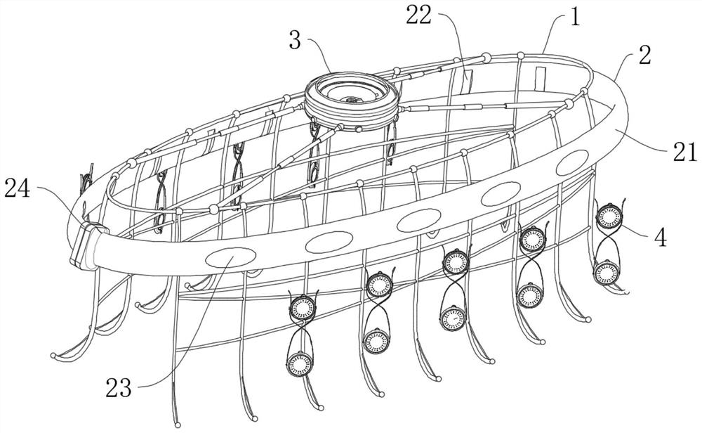
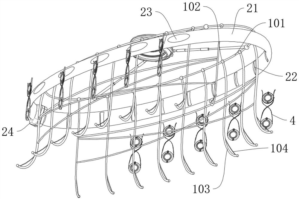
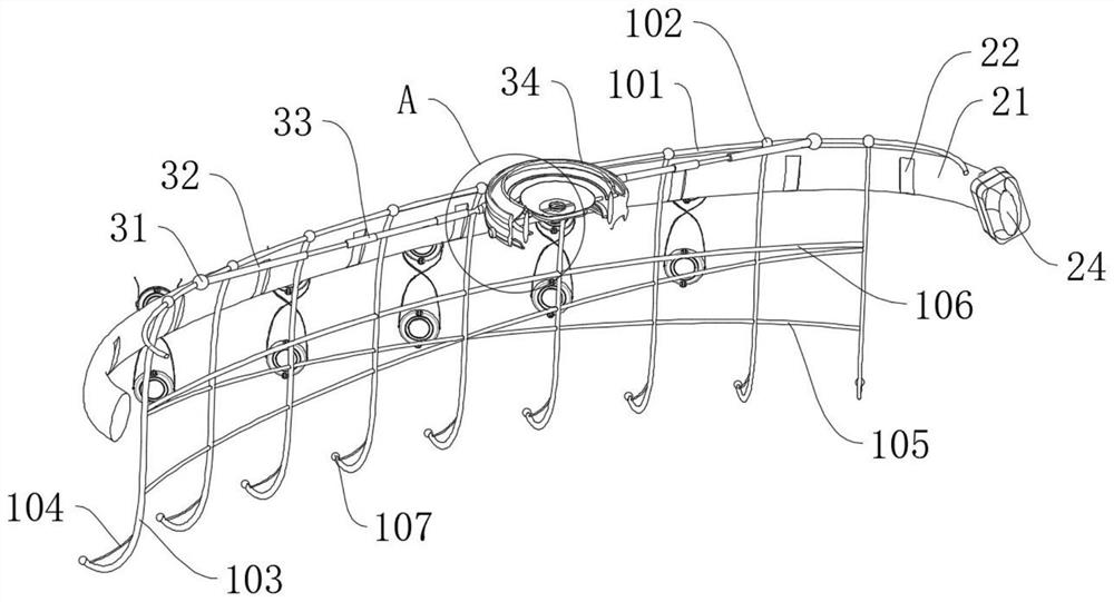
The invention discloses an artificial mitral valve suture-free automatic implanter for cardiology department, which comprises a wound expanding mechanism for supporting and opening the heart wound of a patient, a holding mechanism for medical personnel to hold an artificial mitral valve membrane is arranged outside the wound expanding mechanism, and a suspension type mitral valve implanting mechanism is arranged at the top of the wound expanding mechanism. The wound expanding mechanism further comprises an annular elastic alloy frame, the outer wall of the annular elastic alloy frame is connected with a plurality of torsional spring type connecting pins, and the annular elastic alloy frame is hinged to a plurality of wound expanding supporting cantilevers used for expanding the heart wound of a patient through the torsional spring type connecting pins; the suspension type mitral valve implanting mechanism comprises a universal hinge connecting piece, the universal hinge connecting piece is connected to the outer wall of an annular elastic alloy frame, and the annular elastic alloy frame is hinged to a bearing type rod body fixing base used for supporting through the universal hinge connecting piece. The end, away from the universal hinge connecting piece, of the bearing type rod body fixing base is connected with a hydraulic telescopic rod.

Description

technical field [0001] The invention relates to the technical field of heart valves in the Department of Cardiology, more specifically, the invention relates to a suture-free automatic implanter for an artificial mitral valve used in the Department of Cardiology. Background technique [0002] The mitral valve is the left atrioventricular valve, which is attached to the left fibrous atrioventricular annulus. It is formed by the folds of the endocardium. There are two valves. The one located on the anteromedial side is the anterior cusp valve, which is larger and is often called the large valve. It is the boundary mark between the inflow tract and the outflow tract of the left ventricle; the posterior cusp valve is smaller and is often called a small valve located on the posterolateral side. There is a small accessory valve between the two valves. There are many tendons connected to the papillary muscle at the tip, edge and chamber surface. When the ventricle contracts, the mi...

Claims


Application Information

Patent Timeline
IPC IPC(8): A61B17/02A61F2/24
CPCA61B17/0293A61F2/2427A61F2/24
Inventor 邹承伟朱小龙
Owner 邹承伟
Why Eureka
Try Eureka