
Flow type electrolytic tank for photoelectrocatalytic reaction

A photoelectrocatalytic, flow-type technology, applied in the direction of electrolytic components, electrolytic process, electrodes, etc., can solve the problem of low efficiency of photocatalytic reaction

Active Publication Date: 2022-01-21
CHINA UNIV OF PETROLEUM (EAST CHINA)
View PDF8 Cites 1 Cited by
  • Summary
  • Abstract
  • Description
  • Claims
  • Application Information

AI Technical Summary

Problems solved by technology

[0006] The purpose of the present invention is to provide a flow type electrolytic cell for photocatalytic reaction, to alleviate the technical problem of low photocatalytic reaction efficiency in the prior art

Method used


Image

  • Flow type electrolytic tank for photoelectrocatalytic reaction
  • Flow type electrolytic tank for photoelectrocatalytic reaction
  • Flow type electrolytic tank for photoelectrocatalytic reaction

Examples


Embodiment Construction

[0033] The technical solutions of the present invention will be clearly and completely described below in conjunction with the accompanying drawings. Apparently, the described embodiments are some of the embodiments of the present invention, but not all of them. Based on the embodiments of the present invention, all other embodiments obtained by persons of ordinary skill in the art without making creative efforts belong to the protection scope of the present invention.

[0034] In describing the present invention, it should be understood that the terms "center", "longitudinal", "transverse", "length", "width", "thickness", "upper", "lower", "front", " Back", "Left", "Right", "Vertical", "Horizontal", "Top", "Bottom", "Inner", "Outer", "Clockwise", "Counterclockwise", "Axial" , "radial", "circumferential" and other indicated orientations or positional relationships are based on the orientations or positional relationships shown in the drawings, which are only for the convenienc...


PUM


Abstract

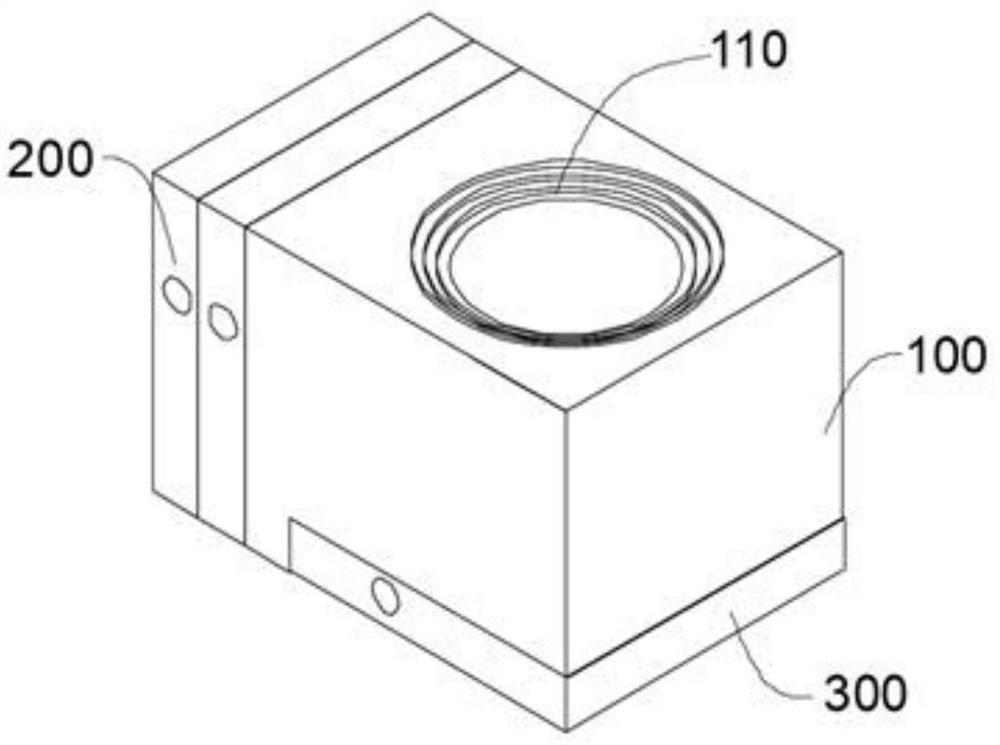
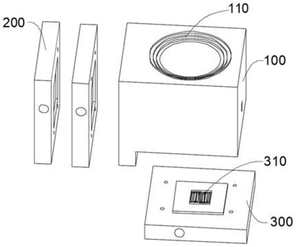
The invention provides a flow type electrolytic tank for photoelectrocatalysis reaction, and relates to the technical field of photoelectrocatalysis equipment. The flow type electrolytic tank for the photoelectrocatalytic reaction comprises a cathode chamber, an anode chamber and a gas chamber, the anode chamber is connected to one side of the cathode chamber, the gas chamber is connected to the bottom of the cathode chamber, the anode chamber is communicated with the cathode chamber, and the gas chamber is communicated with the cathode chamber; a proton exchange membrane is arranged between the anode chamber and the cathode chamber; a working electrode and a waterproof gas-permeable membrane are arranged between the cathode chamber and the gas chamber, the waterproof gas-permeable membrane is located between the working electrode and the gas chamber, and a catalyst is loaded on the working electrode; a light window is formed in the top of the cathode chamber, and a light-transmitting plate is arranged at the light window. The technical effect of improving the photoelectric catalytic reaction efficiency is achieved.

Description

technical field [0001] The invention relates to the technical field of photocatalytic equipment, in particular to a flow electrolytic cell for photocatalytic reaction. Background technique [0002] The photoelectrocatalytic reaction refers to the oxidation-reduction reaction of the photogenerated electron-hole pairs generated by light irradiation on the semiconductor surface in contact with the electrolyte, separated by the electric field of the semiconductor / electrolyte junction, and the ions in the solution. [0003] Photocatalytic reaction is a special type of catalytic reaction, which can directly convert light energy into chemical energy. The commonly used semiconductor material is a photoelectrode, which plays the role of light absorption and catalysis. Depending on the type of semiconductor, the photoanode and photocathode can be separated. Among them, n-type semiconductors are electron-rich, which is conducive to catalytic oxidation reactions, and are often used as ...

Claims


Application Information

Patent Timeline
Patent Type & Authority Applications(China)
IPC IPC(8): C25B9/50C25B11/032
CPCC25B9/50C25B11/032
Inventor 王虹智吴明铂王照亮杨中学赵悦竹
Owner CHINA UNIV OF PETROLEUM (EAST CHINA)
Learn More