
Rapid mold changing device of injection molding machine and injection molding machine

An injection molding machine, fast technology, applied in the field of powder metallurgy, can solve the problems of low efficiency of injection molding machine, difficult to effectively guarantee the mold loading time, etc., to achieve the effect of improving efficiency, simplifying the procedure of mold change, and saving working time

Active Publication Date: 2022-01-21
NINGBO LISONG INJECTION MOLDING TECH CO LTD
View PDF6 Cites 0 Cited by
  • Summary
  • Abstract
  • Description
  • Claims
  • Application Information

AI Technical Summary

Problems solved by technology

[0005] The problem to be solved by the present invention is to provide a quick mold changing device for an injection molding machine and an injection molding machine, which can solve the problem that the efficiency of the mold loading process of the existing injection molding machine is low, and the length of the mold loading time is difficult to be effectively guaranteed.

Method used


Image

  • Rapid mold changing device of injection molding machine and injection molding machine
  • Rapid mold changing device of injection molding machine and injection molding machine
  • Rapid mold changing device of injection molding machine and injection molding machine

Examples


Embodiment 1

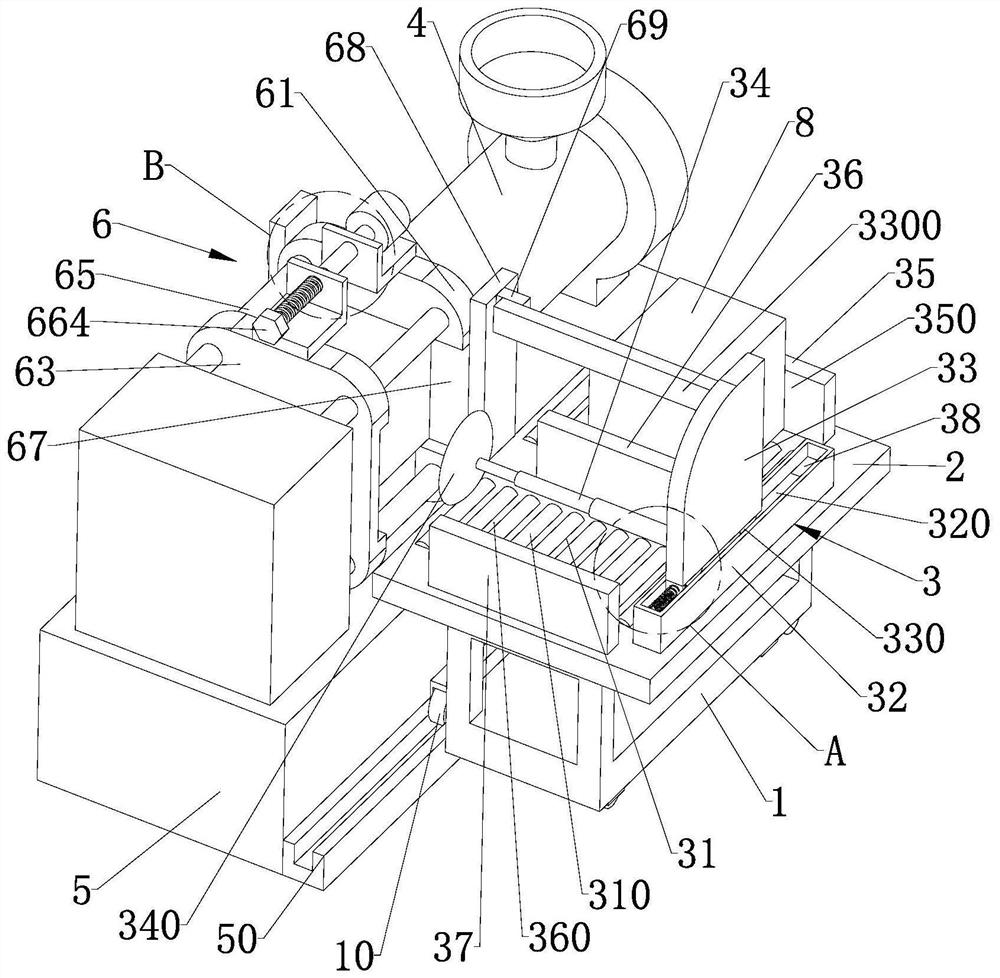
[0029] refer to Figure 1-Figure 3 , the present invention provides the following technical solutions: a rapid mold change device for injection molding machines, including a bottom car 1, an operating table 2 and a mold change assembly 3, the side wall of the bottom car 1 is provided with auxiliary rollers 10; The console 2 is equipped with a mold changing assembly 3; wherein, the cooperation between the bottom car 1 and the mold changing assembly 3 helps the injection molding machine to replace the mold.

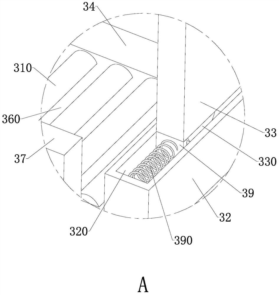
[0030] refer to Figure 1-Figure 2 , the mold change assembly 3 includes two sets of rolling parts 31 arranged on the upper end surface of the console 2, each set of rolling parts 31 is composed of several rollers 310 evenly distributed; wherein, one rolling part 31 is used to help dismounting from the injection molding machine The original mold 7 that comes down moves, and another rolling part 31 is used for helping to move new mold 8 to be assembled on the injection mold...

Embodiment 2

[0037] The present invention also provides an injection molding machine, comprising a body 4 and a base 5, the body 4 is installed on the base 5, and a clamping mechanism 6 arranged on the body 4 for fixing the mould, the side wall of the base 5 is provided with a slideway 50 , the auxiliary roller 10 slides in the slideway 50; wherein, the sliding and the auxiliary roller 10 cooperate with each other, so that the bottom vehicle 1 will not shift when moving, thereby making the mold changing process more smooth.

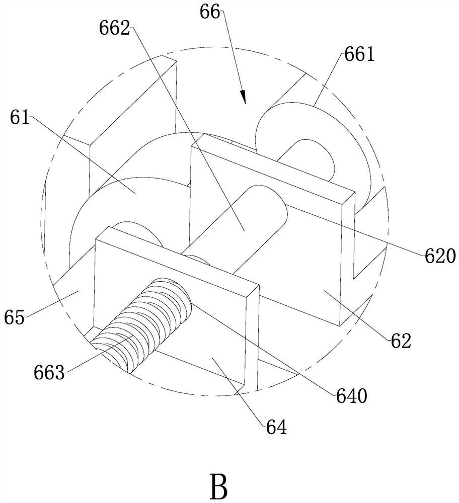
[0038] refer to figure 1 and image 3 , the clamping mechanism 6 includes a fixed template 61, a fixed part 62 arranged on the fixed template 61, a movable template 63, a movable part 64 arranged on the movable template 63, a guide rod 65 and an adjustment for connecting the fixed part 62 and the movable part 64 Part 66, the opposite side walls of the fixed template 61 and the movable template 63 are provided with grooves 67 that match the mould. Offset, thereby aff...


PUM


Abstract

The invention relates to the technical field of powder metallurgy, and particularly discloses a rapid mold changing device of an injection molding machine. The device comprises a bottom vehicle, an operation table and a mold changing assembly. An auxiliary roller is arranged on the side wall of the bottom vehicle. The operation table is installed on the bottom vehicle, and the mold changing assembly is installed on the operation table. The mold changing assembly comprises two sets of rolling parts arranged on the upper end face of the operation table, and each set of rolling part is composed of a plurality of rolling columns which are evenly distributed. The mold changing assembly further comprises a mounting part and a sliding plate, and the mounting part is fixed to the upper end face of the operation table. According to the rapid mold changing device of the injection molding machine and the injection molding machine provided by the invention, a clamping mechanism in the injection molding machine is matched with the rapid mold changing device of the injection molding machine, so that the mold changing procedure of the injection molding machine is simplified, the whole process is mechanically automatic, the trouble caused by manual operation is avoided, the working time is saved, and the mold changing efficiency of the injection molding machine is improved; and certain practicability is achieved.

Description

technical field [0001] The invention relates to the technical field of powder metallurgy, in particular to a quick mold changing device for an injection molding machine and an injection molding machine. Background technique [0002] Injection molding machine is the main equipment for manufacturing compression molding products. When working, it is necessary to assemble and replace the mold used for product molding; at present, the traditional bolt and platen type manpower is used to install and disassemble the mold on the injection molding machine. Operation, since this method is manually installed by the molder during the entire mold changing process, it is limited by the experience, physical strength, and labor time of the molder, and the efficiency of the mold loading process is low. The length of time is difficult to be effectively guaranteed, so that the scope of use of the injection molding machine has certain limitations. [0003] In view of the above problems, the pr...

Claims


Application Information

Patent Timeline
Patent Type & Authority Applications(China)
IPC IPC(8): B29C45/17
CPCB29C45/1756Y02P70/10
Inventor 汪军建徐丰
Owner NINGBO LISONG INJECTION MOLDING TECH CO LTD
Learn More