Infusion tube medical waste recovery device for surgical department

A medical waste and recovery device technology, applied in transportation and packaging, solid waste removal, grain processing, etc., can solve the problems of infection and low efficiency, and achieve the effect of thorough cleaning

Pending Publication Date: 2022-01-21
娄忠定
View PDF0 Cites 0 Cited by
  • Summary
  • Abstract
  • Description
  • Claims
  • Application Information

AI Technical Summary

Problems solved by technology

[0005] In order to overcome the shortcomings of low efficiency and risk of infection in the existing recovery methods, the technical problem is to provide a medical waste recovery device for infusion tubes in surgical departments that can quickly crush infusion tubes for easy collection and avoid infection

Method used


Image

  • Infusion tube medical waste recovery device for surgical department
  • Infusion tube medical waste recovery device for surgical department
  • Infusion tube medical waste recovery device for surgical department

Examples


Embodiment 1

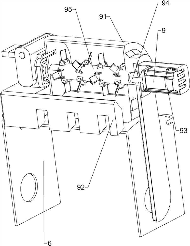
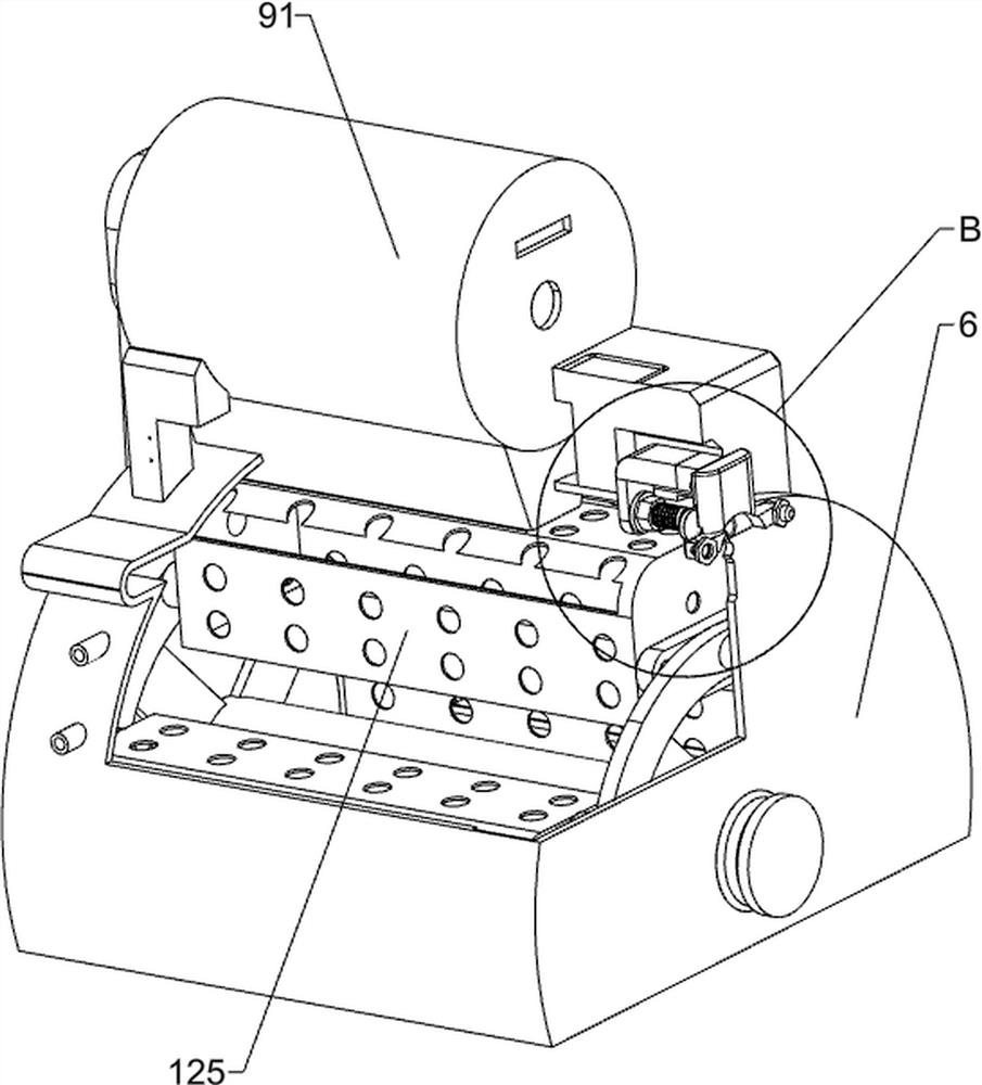
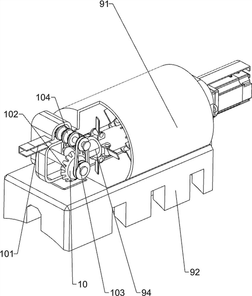
[0035] A kind of surgical department infusion tube medical waste recycling device, such as Figure 1-17 As shown, it includes a support box 1, a top cover plate 2, a support base 3, a heat dissipation top window 4, a start button 51, a stop button 52, a storage cylinder 6, a fixed frame 7, a blanking opening and closing plate 8, an electromagnetic lock 81, Locking button 82, crushing mechanism 9 and feeding mechanism 10, top cover 2 is provided on the top of support box 1, support base 3 is provided on the bottom of support box 1, heat dissipation top window 4 is provided on top cover 2, and support box The upper left part of the front side of the body 1 is provided with a start button 51, the upper left part of the front side of the support box body 1 is provided with a stop button 52, and the front and rear sides of the upper part of the support box body 1 are provided with fixed mounts 7, between the front and rear two fixed mounts 7 A storage cylinder 6 is provided, a blan...

Embodiment 2

[0042] On the basis of Example 1, such as Figure 6 As shown, a cleaning mechanism 11 is also included. The cleaning mechanism 11 includes an installation chassis 111, a waste water tank 112, a clean water tank 113, a water pump 114, a spherical solenoid valve 115 and a liquid level sensor 116. Underframe 111, a waste water tank 112 is provided at the front of the installation underframe 111, a clean water tank 113 is provided at the rear of the installation underframe 111, a water pump 114 with a water pipe is connected between the left side of the clean water tank 113 and the left side of the storage cylinder 6, A spherical solenoid valve 115 with a water pipe is connected between the left side of the waste water tank 112 and the left side of the storage cylinder 6 , and a liquid level sensor 116 is provided at the rear right side of the storage cylinder 6 .

[0043] When using this device, the staff externally connects the water pipe to the clean water tank 113. After the s...


PUM


Abstract

The invention relates to a medical waste recovery device, in particular to an infusion tube medical waste recovery device for the surgical department. According to the infusion tube medical waste recovery device for the surgical department, an infusion tube can be rapidly crushed to be conveniently collected, and meanwhile infection can be avoided. The infusion tube medical waste recovery device for the surgical department comprises a supporting box body; a top cover plate mounted on the supporting box body; and a supporting base mounted on the supporting box body. The infusion tube can be crushed through a crushing mechanism, the infusion tube can be automatically conveyed into a sealing cylinder to be crushed through a feeding mechanism, medicine residues left on the crushed infusion tube can be cleaned through a cleaning mechanism, a certain amount of fragments can be gradually conveyed to the lower portion of a storage cylinder through a separation mechanism to be cleaned, and meanwhile workers can taken out the fragments conveniently; and through an anti-toppling mechanism, the supporting frame and a separation box body can be blocked, and the fragments are prevented from being poured out.

Description

technical field [0001] The invention relates to a medical waste recovery device, in particular to a surgical department infusion tube medical waste recovery device. Background technique [0002] Disposable infusion set is a common medical consumable. After aseptic treatment, a channel between vein and medicinal liquid is established for intravenous infusion. Generally, it is composed of eight parts such as intravenous needle or injection needle, needle cap, infusion hose, liquid medicine filter, flow rate regulator, drip pot, bottle stopper piercer, and air filter. The infusion hoses therein need to be recycled after use. [0003] When recycling, in order to save space, the infusion tubes are generally crushed. At present, when the infusion tubes are crushed, they are generally crushed manually using a crushing machine and then poured out, and then collected manually. The operation is cumbersome and the efficiency is not high, and a large amount of drug residue or bacteria...

Claims


Application Information

Patent Timeline
IPC IPC(8): B02C4/10B02C4/28B02C4/42B02C23/02B02C25/00B08B3/10B09B3/35B09B101/65
CPCB02C4/10B02C4/28B02C4/42B02C23/02B02C25/00B08B3/104B08B3/044B09B3/00B02C2201/06
Inventor 娄忠定
Owner 娄忠定
Why Eureka
Try Eureka