
Distributed power flow controller power unit

A technology of power flow controller and power unit, applied in the field of power system, can solve the problems of limited application, complex structure, high cost, and achieve the effects of flexible installation, improved heat dissipation efficiency, and compact structure

Pending Publication Date: 2022-01-18
NR ENG CO LTD +2
View PDF0 Cites 0 Cited by
  • Summary
  • Abstract
  • Description
  • Claims
  • Application Information

AI Technical Summary

Problems solved by technology

At present, the unified power flow controller is mainly used in the power grid. Its powerful functions and superior characteristics can effectively impr

Method used


Image

  • Distributed power flow controller power unit
  • Distributed power flow controller power unit
  • Distributed power flow controller power unit

Examples


Embodiment Construction

[0025] The technical solution and beneficial effects of the present invention will be described in detail below in conjunction with the accompanying drawings, so as to better understand the solution of the present invention and its advantages in various aspects. However, the specific embodiments and examples described below are for the purpose of illustration only, rather than limiting the present invention.

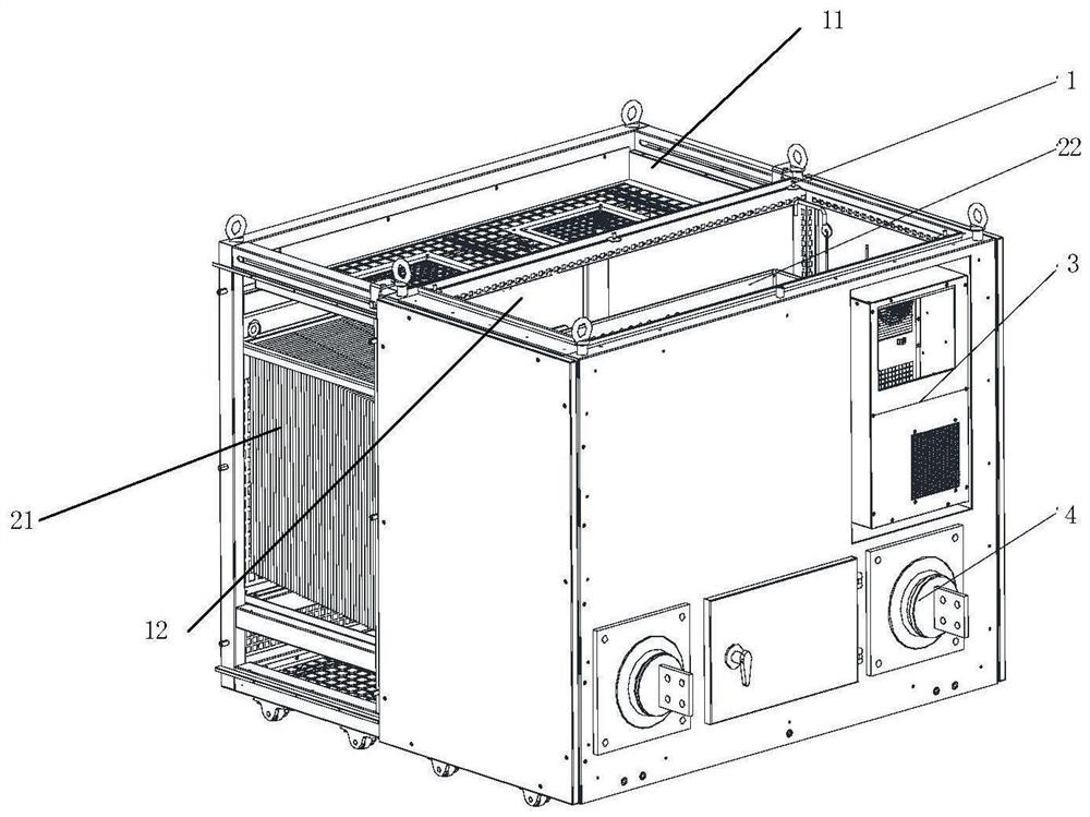
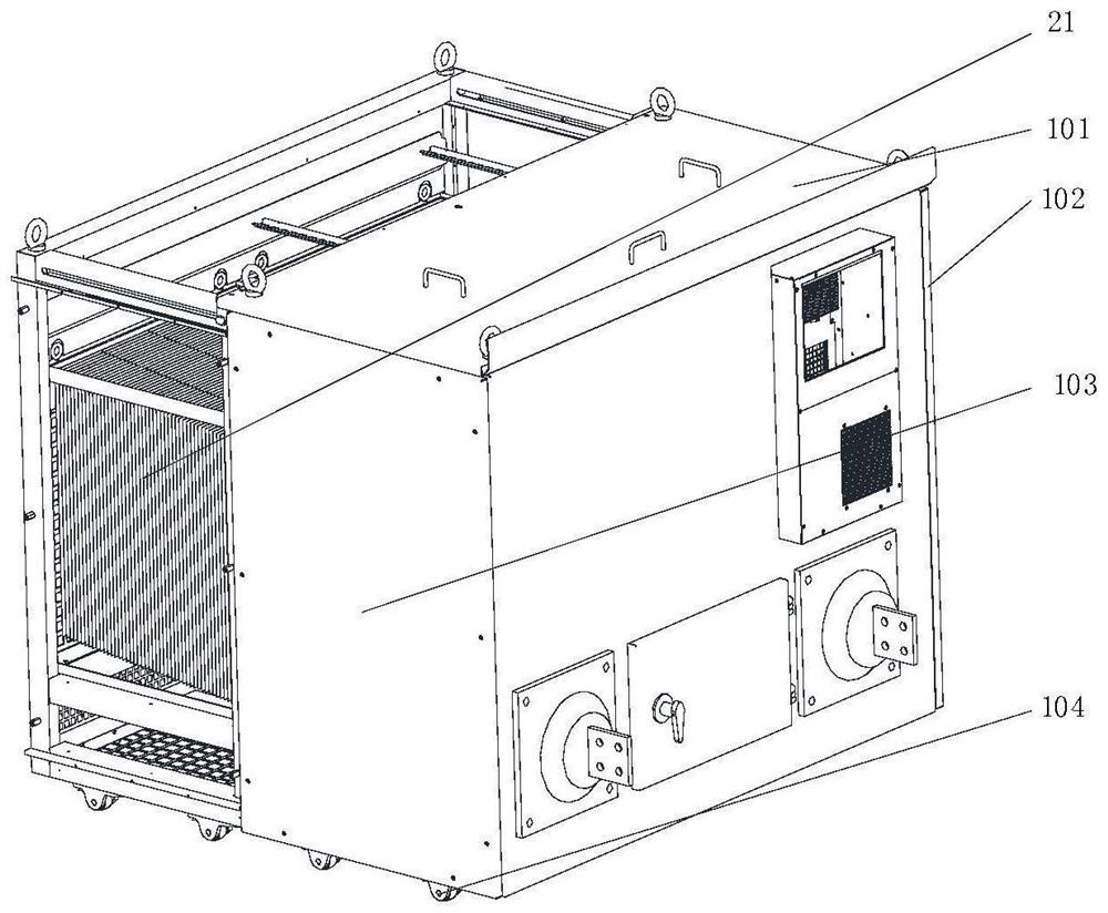
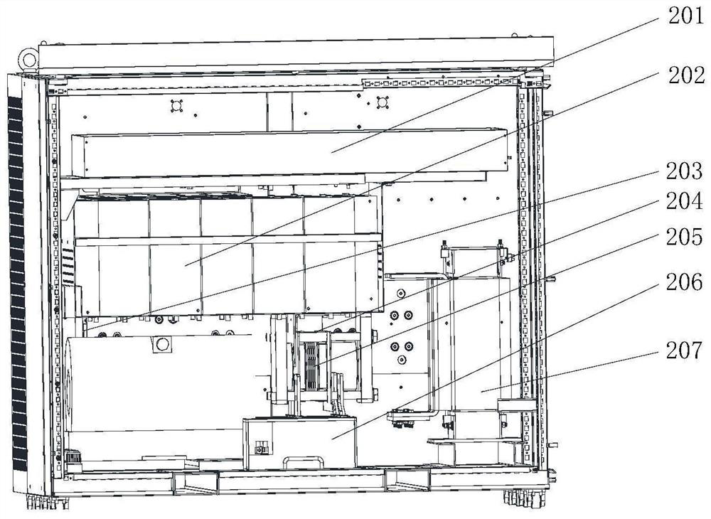
[0026] Such as figure 1 with Figure 4 As shown, the present invention provides a distributed power flow controller power unit. The power unit of the distributed power flow controller includes: a box body 1 , a variable flow control unit, an air conditioner 3 and a wall bushing 4 . Wherein, the box body 1 includes a cooling bin 11 and a control bin 12 , and the outside of the box body 1 and the side of the control bin are regarded as the front of the box body 1 . The variable flow control unit includes a radiator 21 and a variable flow control assembly 22 . The radia...


PUM


Abstract

The invention relates to a distributed power flow controller power unit, which comprises: a box body which comprises a heat dissipation bin and a control bin, wherein the outer side of the box body is regarded as the front face of the box body by taking the control bin as the side face; a variable flow control unit, which comprises a radiator and a variable flow control assembly, wherein the radiator is installed in the heat dissipation bin of the box body; a variable flow control assembly, which is installed in a control bin of the box body; an air conditioner, which is mounted on the front surface of the box body; and a wall bushing, which is mounted on the front surface of the box body. The distributed power flow controller power unit is compact in structure, flexible to install and high in overall heat dissipation efficiency, and meets the requirement for stable operation of a power grid.

Description

technical field [0001] The invention belongs to the technical field of power systems, and in particular relates to a distributed power flow controller power unit. Background technique [0002] With the continuous expansion of the scale of power grid construction and the diversification of new energy and other energy access methods, problems such as unbalanced distribution of power generation and load in the grid area, and uneven distribution of power flow of power transmission and transformation equipment have become increasingly prominent. Some power supply sections are heavily loaded. The transmission capacity of other sections is underutilized, and the overall power supply capacity of the grid is difficult to be fully utilized, which reduces the overall efficiency of the grid. At the same time, due to the restrictions of urban planning, it is increasingly difficult to transform transmission lines and expand power grids. [0003] Therefore, how to improve the overall util...

Claims


Application Information

Patent Timeline
IPC IPC(8): H02M7/00H05K7/14H05K7/20H02J3/18
CPCH02M7/003H05K7/1432H05K7/2089H05K7/20927H02J3/1814Y02E40/10
Inventor 张国栋盛晓东张中胜于海波段军叶晗杨幸辰谢晔源田杰
Owner NR ENG CO LTD
Learn More