Digital array method and system integrating DBF direction finding and interferometer direction finding

A digital array and interferometer technology, applied in the field of antennas, can solve the problems of large-scale deblurring of interferometers, interferometer false detection, and large-scale defuzzification, and achieve the effect of excellent overall direction finding performance and good stability.

Pending Publication Date: 2022-01-18
NANJING CHANGFENG AEROSPACE ELECTRONICS SCI & TECH
View PDF0 Cites 0 Cited by
  • Summary
  • Abstract
  • Description
  • Claims
  • Application Information

AI Technical Summary

Problems solved by technology

The existing scheme virtual baseline interferometer constructs a virtual baseline. However, in order to ensure the measurement accuracy requirements, etc., limited by the size of the array, the interferometer is often unable to achieve large-scale deambiguation.
The staggered baseline phase interferometer scheme can break through the limitation of the baseline length, and achieve a large range of defuzzification under the premise of ensuring the accuracy of direction finding, but it is still difficult to achieve ±90° omnidirectional defuzzification
In addition, no matter what kind of phase interferometer, there is an unsolvable disadvantage. With the deterioration of the signal-to-noise ratio of the received signal, the interferometer will have a large number of mismeasurements.

Method used


Image

  • Digital array method and system integrating DBF direction finding and interferometer direction finding
  • Digital array method and system integrating DBF direction finding and interferometer direction finding
  • Digital array method and system integrating DBF direction finding and interferometer direction finding

Examples


Embodiment Construction

[0042] The present invention will be further described below in conjunction with the accompanying drawings. The following examples are only used to illustrate the technical solution of the present invention more clearly, but not to limit the protection scope of the present invention.

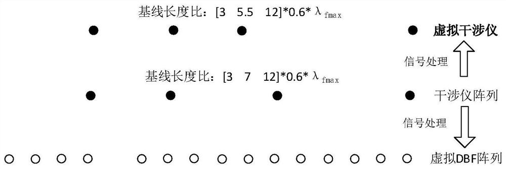
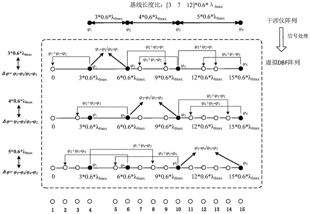
[0043] The design of the three-baseline four-unit interferometer based on the present invention constructs a virtual interferometer and a virtual DBF array (15 array elements) through virtual baseline technology and sparse DBF processing technology to realize wide bandwidth angle (±90°) high-probability defuzzification interferometer measurement Direction and DBF direction finding, such as figure 1 As shown, the specific method is as follows:

[0044] For the target broadband signal, the element spacing of the interferometer array is

[0045] X=[3 7 12]×0.6λ fmax lambda fmax is the wavelength corresponding to the highest signal frequency.

[0046] First, through the optimization of intellig...


PUM


Abstract

The invention discloses a digital array method and system integrating DBF direction finding and interferometer direction finding. The method comprises the steps of determining an interferometer array of a target signal through a current interferometer, and determining the array element spacing of the interferometer array and the phase of a receiving signal of each array element in the interferometer array, optimizing the array element spacing of the interferometer array, and performing virtual positive element processing according to the optimized array element spacing of the interferometer array to obtain a virtual interferometer, performing sparse DBF processing on the phase of the array element receiving signal to obtain a virtual DBF array, acquiring the signal-to-noise ratio of the target broadband signal, when the signal-to-noise ratio of the target signal is higher than a threshold value, adopting the virtual interferometer for direction finding, and when the signal-to-noise ratio of the target broadband signal is not higher than the threshold value, adopting the virtual DBF array for direction finding. The method has the advantages that through sparse DBF processing and virtual array element processing, direction finding of a DBF system can be achieved while broadband wide-angle (+/-90 degrees) high-probability ambiguity resolution interferometer measurement can be achieved, and the overall direction finding performance is better.

Description

technical field [0001] The invention relates to a digital array method and system combining DBF direction finding and interferometer direction finding, belonging to the technical field of antennas. Background technique [0002] The process of determining the direction of the radiation source by intercepting radio signals is called radio direction finding, or direction finding for short. Direction finding is one of the important tasks of electronic countermeasure reconnaissance. It has many functions in electronic countermeasures: providing reliable basis for the sorting and identification of radiation sources; providing guidance for electronic jamming and destroying attacks; providing threat warning for combatants; The location of the radiation source provides parameters and the like. The essence of direction finding in electronic countermeasures reconnaissance is to determine or estimate the direction of arrival of radiation sources in space and the direction of arrival of...

Claims


Application Information

Patent Timeline
Patent Type & Authority Applications(China)
IPC IPC(8): G01S3/48
CPCG01S3/48
Inventor 胡梦中张道成袁淼
Owner NANJING CHANGFENG AEROSPACE ELECTRONICS SCI & TECH
Why Eureka
Try Eureka