Car lamp lighting system
A lighting system and vehicle lamp technology, which is applied in the optical field, can solve the problems of inability to take into account the high-brightness lighting effects of low beam, high beam and high beam, poor heat dissipation effect of integrated lens headlights for far and near beams, power limitation of light source power, etc. Avoid the reduction of light collection efficiency, high instantaneous conversion efficiency, and good light shape effect
- Summary
- Abstract
- Description
- Claims
- Application Information
AI Technical Summary
Problems solved by technology
Method used
Image
Examples
Embodiment 1
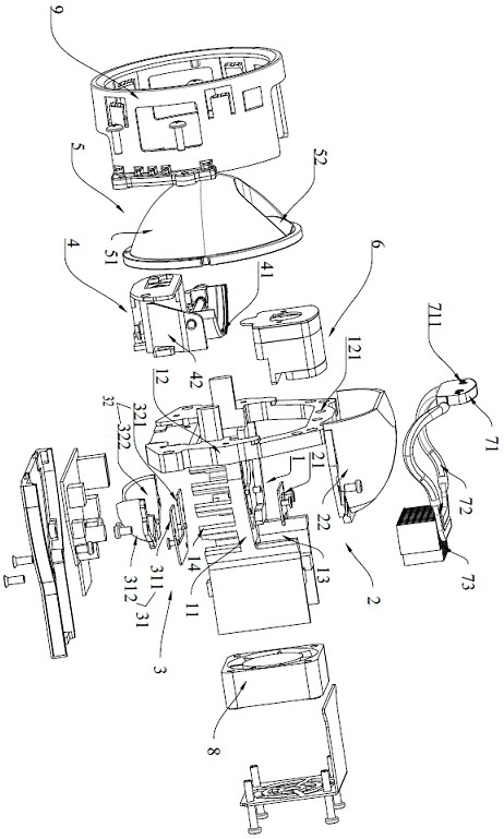
[0039] Such as figure 1As shown, a lighting system for vehicle lights, comprising: a heat dissipation base 1, a low beam component 2, a high beam component 3, a high beam strengthening component 6, a light cutting component 4 and a light output lens 5 arranged on the heat dissipation base 1;
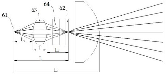
[0040] Such as figure 2 As shown, the high beam strengthening component 6 includes a laser 61, a wavelength conversion device 62 for converting the light wavelength of the laser 61, and a biconvex lens 63 arranged between the laser 61 and the wavelength conversion device 62; The convex lens 63 is located between the laser 61 and the light-emitting lens 5;
[0041] The high beam component 3 includes a first high beam component 31 and a second high beam component 32; upper dislocation;
[0042] The light beams of the low beam component 2, the high beam component 3 and the high beam strengthening component 6 are all emitted through the light exit lens 5;
[0043] The light-cutting comp...
Embodiment 2
[0077] The structure and principle of this embodiment are similar to those of Embodiment 1, the difference lies in that the installation position of the high beam component 3 and the orientation of the light emitting surface in this embodiment are different.
[0078] Specifically, such as Figure 7 As shown, the heat dissipation base in this embodiment includes a first installation surface 111 and a second installation surface 112, the first installation surface 111 is higher than the second installation surface 112, and the low beam component 2 is installed on the first installation surface 111 , the high beam component 3 is installed on the second installation surface 112 . The second installation surface 112 is parallel to the first installation surface 111 or the second installation surface 112 forms a certain angle with the first installation surface 111, and the size of the included angle is 0︒~60︒. The maximum height does not exceed the height of the first mounting sur...
Embodiment 3
[0082] This embodiment is similar in structure and principle to Embodiment 1 and Embodiment 2, the difference is that the first high beam component 31 includes a first high beam illuminant 311 and a first total reflection lens 313, and the second high beam Component 32 comprises the second high-beam illuminant 321 and the second total reflection lens 323; The first high-beam illuminant 311 and the second high-beam illuminant 321 are respectively connected by the first high-beam illuminant 313 and the second total reflection lens 323. The light rays are collected and converged at the focus position of the light-emitting lens 5 . Both the first high-beam component and the second high-beam component use total reflection lenses to collect light from the high-beam illuminant, on the one hand, they can fully stagger the low-beam illuminant, the first high-beam illuminant, and the second high-beam illuminant, The heat dissipation effect is fully guaranteed. On the other hand, the tot...
PUM
| Property | Measurement | Unit |
|---|---|---|
| length | aaaaa | aaaaa |
| length | aaaaa | aaaaa |
| length | aaaaa | aaaaa |
Abstract
Description
Claims
Application Information
 - Generate Ideas
- Intellectual Property
- Life Sciences
- Materials
- Tech Scout
- Unparalleled Data Quality
- Higher Quality Content
- 60% Fewer Hallucinations
Browse by: Latest US Patents, China's latest patents, Technical Efficacy Thesaurus, Application Domain, Technology Topic, Popular Technical Reports.
© 2025 PatSnap. All rights reserved.Legal|Privacy policy|Modern Slavery Act Transparency Statement|Sitemap|About US| Contact US: help@patsnap.com


