
Comprehensive test station used for detecting hydraulic pump

A comprehensive test, hydraulic pump technology, applied in the field of comprehensive test station, can solve the problems of difficulty in guarantee, inconvenient matching and installation of the pump to be tested on the gear pump test bench, easy to change the test accuracy, etc., to achieve easy disassembly, cleaning or replacement, good The effect of air cooling

Active Publication Date: 2022-01-18
合肥赛源液压件有限公司
View PDF9 Cites 0 Cited by
  • Summary
  • Abstract
  • Description
  • Claims
  • Application Information

AI Technical Summary

Problems solved by technology

[0004] The purpose of this invention is to solve the problem that the current gear pump test bench is not convenient to match and install the pump to be tested, and the oil quality of the hydraulic oil used for the test is easy to deteriorate, which makes it difficult to guarantee the accuracy of the test. comprehensive test station

Method used


Image

  • Comprehensive test station used for detecting hydraulic pump
  • Comprehensive test station used for detecting hydraulic pump
  • Comprehensive test station used for detecting hydraulic pump

Examples


Embodiment Construction

[0037]The following will clearly and completely describe the technical solutions in the embodiments of the present invention with reference to the accompanying drawings in the embodiments of the present invention. Obviously, the described embodiments are only some, not all, embodiments of the present invention. Based on the embodiments of the present invention, all other embodiments obtained by persons of ordinary skill in the art without making creative efforts belong to the protection scope of the present invention.

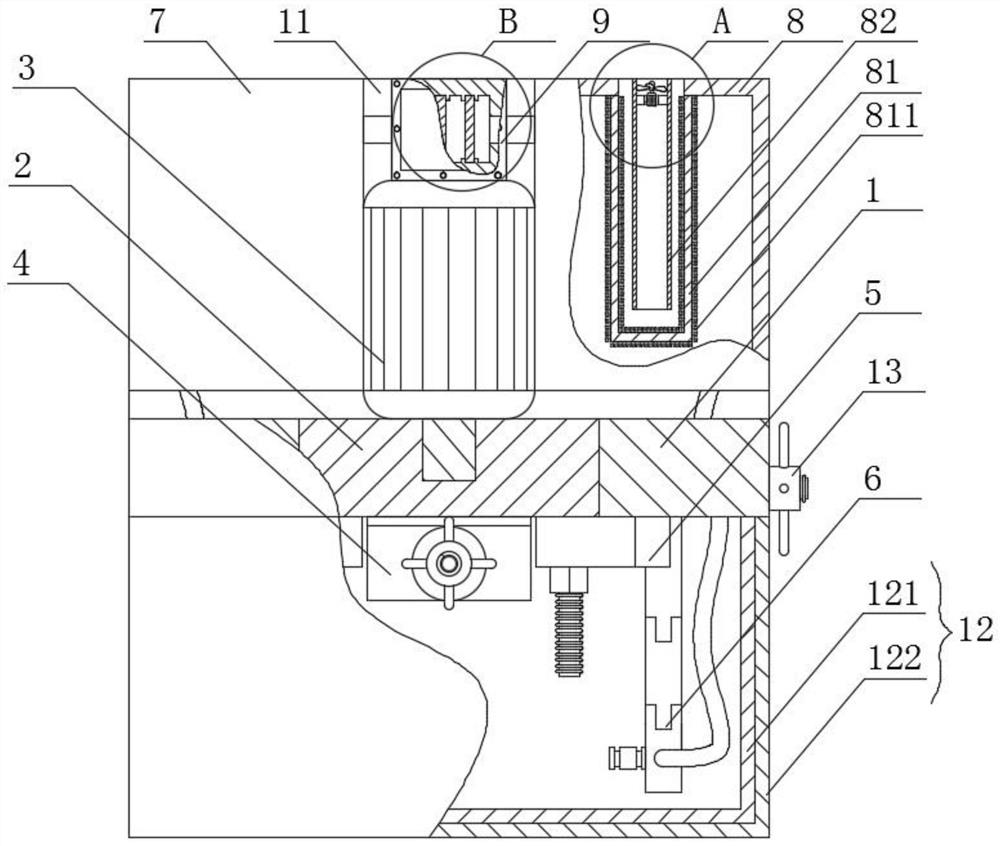
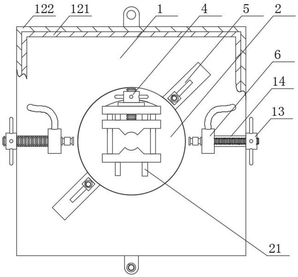
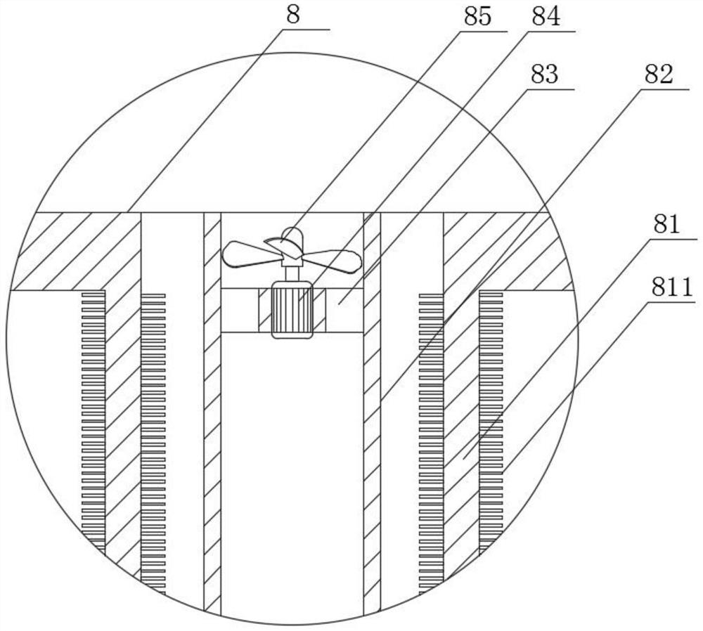
[0038] see Figure 1-7 , the present invention provides a technical solution, a comprehensive test station for testing hydraulic pumps, including a vertical plate 1, a drive motor 3, a rotating disc 2, a shaft connection part 4, a fixed seat 5, an oil circuit connection part 6, The oil inlet tank 7, the oil return tank 8 and the filter box body 9, the bottom end of the back of the vertical plate 1 is connected with the bottom plate 11, and the driving motor 3 i...


PUM


Abstract

The invention relates to the technical field of hydraulic pump test devices, and particularly discloses a comprehensive test station used for detecting a hydraulic pump. A rotating disc rotationally connected to the middle of a vertical plate in a sleeved manner is connected with the power output end of a driving motor, the back faces of an upper clamping plate and a lower clamping plate included in a shaft connecting part are slidably clamped to the front face of the rotating disc in a clamped manner, supporting rods are connected between the upper surface of the lower clamping plate and the lower surface of a base plate, the top end, rotationally connected with a first screw in a sleeving manner, of the upper surface of the upper clamping plate is in threaded sleeved connection with a second rotating sleeve on the upper surface of the base plate, and clamping petals are arranged on the opposite faces of the upper clamping plate and the lower clamping plate correspondingly; fixing seats are used for fixing the to-be-tested pump on the vertical plate, an oil way connecting part is used for connecting a connector with oil inlet and return ports of to-be-tested pumps with different sizes, a filter box body is connected between an oil inlet box and an oil return box, an air cooling mechanism is arranged in the oil return box, and a filter plate in the filter box is detachable; and the problems that the to-be-tested pump cannot be conveniently matched and installed on a gear pump test station, and the test accuracy is difficult to guarantee due to the fact that the oil quality of hydraulic oil for testing easily becomes poor are solved.

Description

technical field [0001] The invention relates to the technical field of hydraulic pump test devices, in particular to a comprehensive test station for testing hydraulic pumps. Background technique [0002] The hydraulic pump is the power component of the hydraulic system. It is driven by an electric motor, sucks oil from the hydraulic oil tank, forms pressure oil and discharges it, and sends it to the actuator. Hydraulic pumps are divided into gear pumps, plunger pumps, vane pumps and screw pumps according to their structure. Among them, the gear pump is the most commonly used. As a power component in the hydraulic system, the performance of the hydraulic pump has a great influence on the performance of the hydraulic system. Therefore, in the production process of the hydraulic pump, the performance of the hydraulic pump needs to be tested. [0003] At present, the hydraulic pump test bench is mainly used for performance testing of hydraulic gear pumps, used to determine th...

Claims


Application Information

Patent Timeline
Patent Type & Authority Applications(China)
IPC IPC(8): F04B51/00F15B21/041F15B21/0423
CPCF04B51/00F15B21/041F15B21/0423
Inventor 毕长虹
Owner 合肥赛源液压件有限公司
Learn More