
Efficient strip cutting device for rubber sheets

A rubber sheet, high-efficiency technology, applied in the direction of metal processing, etc., can solve the problems of increasing labor intensity, inconvenience, fried edges and bulging of workers, and achieve the effect of avoiding curling and fried edges

Inactive Publication Date: 2022-01-18
河南赛仑特液压流体科技有限公司
View PDF0 Cites 0 Cited by
  • Summary
  • Abstract
  • Description
  • Claims
  • Application Information

AI Technical Summary

Problems solved by technology

[0002] The raw material for the production of hydraulic rubber hose is rubber sheet, each sheet of rubber has an area of ​​about one square meter, and is in the shape of a rectangle with irregular edges. Before feeding the material into the extruder, the sheet rubber needs to be cut into strips shape, the traditional cutting equipment has multiple blade saws, strip rolling machines, etc. Such equipment can only cut from one end of the rubber sheet. During the cutting process, the edge of the rubber sheet is irregular and the thickness is not uniform, so it is easy to cut. It causes the rubber sheet to be curled, fried and bulged, which causes the deformation of the cutting tool during the cutting process. At the same time, because the length of the rubber sheet is too long when it is cut into strips, it is inconvenient for subsequent workers to feed materials into the extruder. The rubber strip is cut twice to reduce its length, which is convenient for extruder workers to feed. However, the equipment cutting equipment at this stage does not have this function, and manual secondary cutting is required, and the rubber is increased step by step. The cutting operation steps reduce the production efficiency and increase the labor intensity of the workers. At the same time, there is also the problem that the rubber sheet is not convenient to place in the cutting equipment in the existing equipment.

Method used


Image

  • Efficient strip cutting device for rubber sheets
  • Efficient strip cutting device for rubber sheets
  • Efficient strip cutting device for rubber sheets

Examples


Embodiment Construction

[0016] The specific implementation manners of the present invention will be described in further detail below in conjunction with the accompanying drawings.

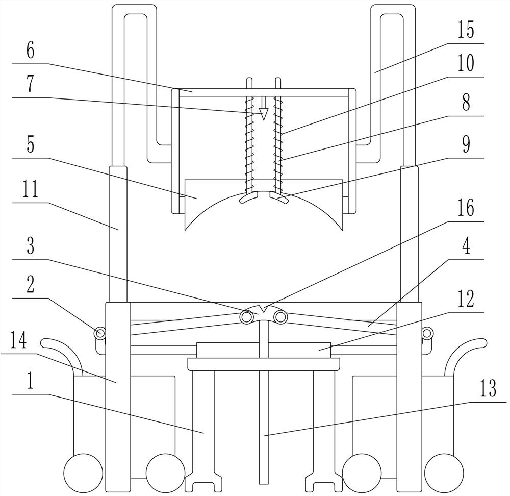
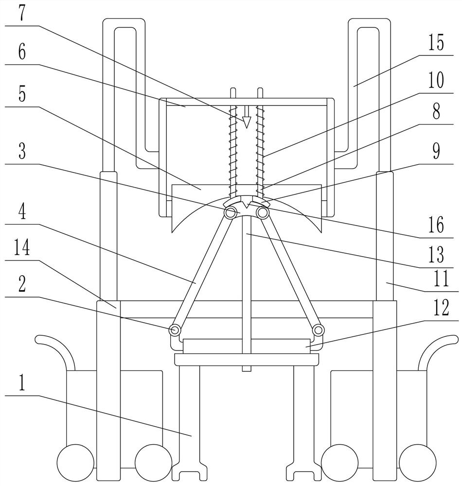
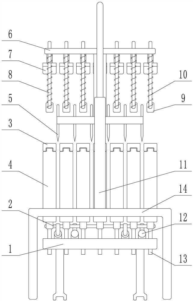
[0017] Depend on Figure 1 to Figure 4 It can be seen that the present invention includes a base 1, and the left and right sides above the base 1 are respectively provided with a support rod 2 in the front and rear directions of the axis. The two support rods 2 can move in opposite directions synchronously. An arc-shaped support body 3, a connecting rod 4 is hinged on the left and right sides of each supporting body 3, and the other end of the connecting rod 4 is hinged on the supporting rod 2 on the corresponding side, and the supporting body 3 is connected with the connecting rods on both sides. 4. Form a support unit. When the support rod 2 moves closer to the middle, the support body 3 is jacked up. When the support rod 2 moves outward, the support body 3 is driven downward. A first Cutter 5, a plurality of first cu...


PUM


Abstract

The invention relates to an efficient strip cutting device for rubber sheets. The device is characterized by comprising a base, wherein supporting rods are arranged on the left side and the right side of the upper part of the base, the two supporting rods can synchronously move oppositely and reversely, a plurality of arc-shaped supporting bodies are evenly distributed at the middle of the end of the base front and back in a spacing manner, and connecting rods are hinged to the left side and the right side of each supporting body; the other end of each connecting rod is hinged to the supporting rod on the corresponding side, a first cutter is arranged above a spacing between every two adjacent supporting bodies, a mounting plate is arranged above the first cutters, and a plurality of second cutters which correspond to the supporting bodies one to one and are arranged over the corresponding supporting bodies are fixed to the mounting plate; the left side and the right side of each second cutter are each provided with a first polished rod in a penetrating and sliding mode, the lower end of each first polished rod is fixedly provided with an arc-shaped plate attached to the arc shape of the upper end of the corresponding supporting body, and each first polished rod is sleeved with a spring; and the left side and the right side of the mounting plate are each provided with a first electric cylinder capable of driving the mounting plate and the corresponding first cutter to move up and down synchronously.

Description

technical field [0001] The invention relates to the field of hydraulic rubber tube production equipment, in particular to a high-efficiency strip cutting device for rubber sheets. Background technique [0002] The raw material for the production of hydraulic rubber hose is rubber sheet, each sheet of rubber has an area of ​​about one square meter, and is in the shape of a rectangle with irregular edges. Before feeding the material into the extruder, the sheet rubber needs to be cut into strips shape, the traditional cutting equipment has multiple blade saws, strip rolling machines, etc. Such equipment can only cut from one end of the rubber sheet. During the cutting process, the edge of the rubber sheet is irregular and the thickness is not uniform, so it is easy to cut. It causes the rubber sheet to be curled, fried and bulged, which causes the deformation of the cutting tool during the cutting process. At the same time, because the length of the rubber sheet is too long wh...

Claims


Application Information

Patent Timeline
Patent Type & Authority Applications(China)
IPC IPC(8): B26D1/06B26D7/02B29C48/25
CPCB26D1/065B26D7/015B26D7/025B29C48/25
Inventor 程昱翔徐哲琳赵地程真真
Owner 河南赛仑特液压流体科技有限公司
Learn More