


Quick Research
Generate reliable direction feasibility study reports for your R&D in just a few steps.

Technical Q&A
Discover and master advanced knowledge NOW. Basics, ideas, possibilities, all at once.

Find Solutions
As an expert in R&D theories, this can generate solutions to your technical problems instantly.

Evaluate Feasibility
Analyze your overall solution with one click, know your potential R&D risks in advance.

Monitor Landscape
Get weekly tech updates, stay abreast of the latest tech innovations and key insights.
Anti-misoperation manual-automatic integrated connecting and locking device for rotating shaft and locking method
An anti-misoperation, locking device technology, applied in mechanical equipment, brake types, etc., can solve the problems of low success rate and stuck in one operation, reduce work intensity and operation accuracy, compact structure, and improve work reliability. Effect
- Summary
- Abstract
- Description
- Claims
- Application Information
AI Technical Summary
Problems solved by technology
Method used
Image

Examples
Embodiment 1
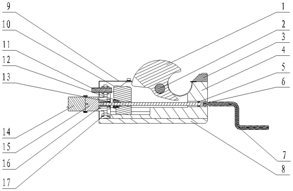
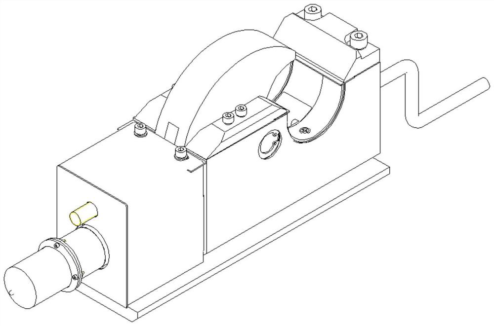
[0048] A specific embodiment of the present invention is disclosed, an anti-error operation of a rotary axis is disclosed, such as Figure 1 to 4As shown, including the lock disc 1, the support 4, the operating lever 6, and the lock block 10; wherein the support 4 is provided with a lock block 10, a locking disk 1 mounting groove, and a lock block 10 set on the operating lever 6. The operating lever 6 rotates to move the lock block 10 in the mounting slot along the operating rod 6, the lock disk 1 is mounted in the mounting groove by the pin shaft 2, and the lock disk 1 can be wound in the mounting groove under the push of the lock block 10. The shaft 2 is rotated; the axis of the operating lever 6 is perpendicular to the axis of the pin shaft 2. Since the lock disk 1 is connected to the support 4 through the pin shaft 2, the pin shaft 2 can be rotated, and the lock block 10 is slid to the mounting groove in the mounting groove by manually or the motor, thereby limiting the lock. T...
Embodiment 2
[0069] In still another embodiment of the present invention, the locking method of the anti-wrong operation of the rotary axis in the first embodiment is disclosed, and the locking method of the locking device is:
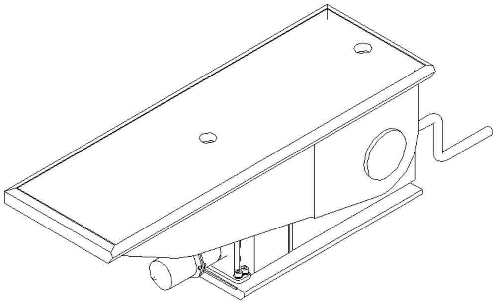
[0070] Step 1: Secure the bottom plate 8 to the external mounting platform.
[0071] Step 2: Turn the operating lever 6, the drive lock block 10 is moved to the unlocked position; mount the rotary shaft to the semi-circular gap of the support 4, the semi-circular gap of the lock disk 1 and the semi-circular dump of the support 4 Head; the drive lock block 10 moves to the locked position to realize the lock of the rotary shaft.
[0072] The operating handle 7 or the motor 14 energizes the drive lock block 10 to move to the unlocked position in the mounting groove in the mounting slot, the lock disk 1 can be freely rotated around the pin shaft 2, mount the rotary shaft to the semi-circular gap of the support 4, lock The disc 1 is rotated, the semicircular gap of the lock...
PUM
 Abstract
Description
Claims
Application Information
 - R&D Engineer
- R&D Manager
- IP Professional
- Industry Leading Data Capabilities
- Powerful AI technology
- Patent DNA Extraction
Browse by: Latest US Patents, China's latest patents, Technical Efficacy Thesaurus, Application Domain, Technology Topic, Popular Technical Reports.
© 2024 PatSnap. All rights reserved.Legal|Privacy policy|Modern Slavery Act Transparency Statement|Sitemap|About US| Contact US: help@patsnap.com