Automobile magneto-rheological brake

A magneto-rheological and brake technology, applied in the direction of brake types, liquid resistance brakes, mechanical equipment, etc., can solve the problem that the braking force is small and cannot meet the requirements of automobile braking

Pending Publication Date: 2022-01-14
TAIZHOU UNIV
View PDF6 Cites 0 Cited by
  • Summary
  • Abstract
  • Description
  • Claims
  • Application Information

AI Technical Summary

Problems solved by technology

[0004] The purpose of the present invention is to provide a magneto-rheological brake for automobiles, which can effectively solve the problem that the braking force provided by the existing brakes is too small and cannot be applied to the braking requirements of automobiles

Method used


Image

  • Automobile magneto-rheological brake
  • Automobile magneto-rheological brake
  • Automobile magneto-rheological brake

Examples


Embodiment Construction

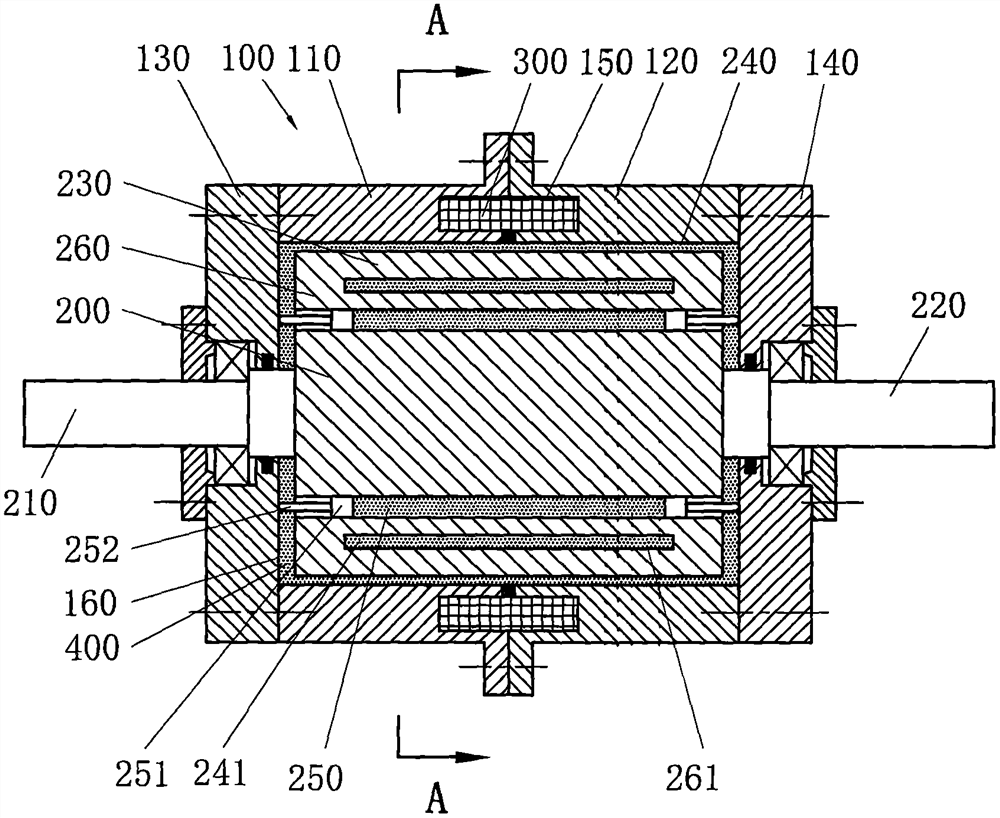
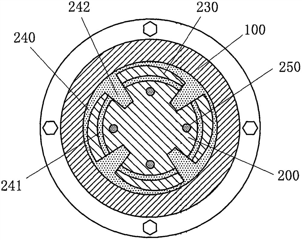
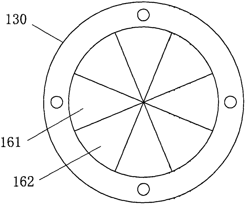
[0022] The automobile magneto-rheological brake includes a stator and a rotor. The stator is provided with a placement chamber, the rotor is arranged in the placement chamber, and the left and right ends of the stator are respectively provided with a left end cover and a right end cover to close the placement chamber. The stator is provided with a coil, and the placement cavity is filled with magnetorheological fluid; the two ends of the rotor are respectively provided with an input shaft and an output shaft, and the input shaft passes through the left end cover and is rotatably connected with the left end cover. The output shaft passes through the right end cover and is rotatably connected with the right end cover; at least two blades are evenly distributed on the outer circumference of the rotor, and a first circulation channel is left between the outer circumference of the blades and the inner side wall of the placement cavity, so There is at least one hydraulic chamber pene...


PUM


Abstract

The invention discloses an automobile magneto-rheological brake which comprises a stator and a rotor. The rotor is arranged in a containing cavity in the stator; a coil is arranged in the stator; the containing cavity is filled with magneto-rheological fluid; at least two blades are evenly distributed on the outer circumferential face of the rotor; a first circulation channel is reserved between the peripheries of the blades and the inner side wall of the containing cavity; at least one hydraulic cavity penetrating through the rotor is formed in the rotor in the axial direction; the hydraulic cavity is also filled with the magneto-rheological fluid; pistons are arranged at the two ends of the hydraulic cavity; sliding rods extending out of the hydraulic cavity are arranged on the pistons; the ends of the sliding rods make contact with a corresponding left end cover or right end cover; concave-convex alternate curved surfaces are arranged on the end faces, facing the rotor, of the left end cover and the right end cover; and when the coil is not powered on, after the rotor rotates, the sliding rods slide along the curved surfaces of the corresponding end covers, and the piston is pushed to move in the axial direction of the rotor. The automobile magneto-rheological brake provided by the invention has the advantages that through the combined action of the blades and the sliding rods, larger braking force is provided for the rotor, and the requirement of an automobile for the braking force is better met.

Description

technical field [0001] The invention relates to an automobile magneto-rheological brake. Background technique [0002] Magneto-rheological fluid is a substance whose normal state is that the liquid will transform into a solid-like state after being subjected to a magnetic field. In the prior art, the characteristics of the magnetorheological fluid are often used to make brakes, and the magnetorheological fluid is filled between the stator and the rotor. When the coil is not energized, the rotor rotates relative to the stator, and when braking is required, the coil is energized to generate a magnetic field, so that the magnetorheological fluid in it turns into a solid state, thereby generating braking force, preventing the rotor from rotating, and achieving braking Effect. [0003] Traditional brakes using magneto-rheological fluids are equipped with blades on the outer periphery of the rotor. When the magneto-rheological fluid turns into a solid state, the contact surface w...

Claims


Application Information

Patent Timeline
Patent Type & Authority Applications(China)
IPC IPC(8): F16D57/00
CPCF16D57/002F16D57/007F16D57/005
Inventor 高雅毕成王鸿云瞿波黄孝盈王泽丰何嘉豪
Owner TAIZHOU UNIV
Why Eureka
Try Eureka