
Double-motor two-gear electric drive axle structure

An electric drive, dual-motor technology, applied in electric power units, power units, control devices, etc., can solve the problems of insufficiently compact built-in structure, inability to meet speed change requirements, poor shifting comfort, etc. The effect of blocking the impact and improving the lifespan

Pending Publication Date: 2022-01-14
江苏华永复合材料有限公司
View PDF11 Cites 2 Cited by
  • Summary
  • Abstract
  • Description
  • Claims
  • Application Information

AI Technical Summary

Problems solved by technology

As a common transmission mechanism, the drive axle is widely used in the field of mechanical and vehicle transmission. In order to adapt to the development of new energy vehicle technology, an electric drive axle driven by a drive motor has appeared. Most of the electric drive axles on the market are in one gear. The electric drive axle has high energy consumption and cannot meet the more complex transmission requirements. The two-speed electric drive axle on the market has a complex structure and does not get rid of the structural constraints of the bevel gear main reducer. The built-in structure is not compact enough, the cost is high, and the volume Large, difficult to arrange in a limited installation space, difficult to apply to vehicles with independent suspension to achieve complete vehicle layout, and the comfort of shifting is poor

Method used


Image

  • Double-motor two-gear electric drive axle structure

Examples


Embodiment 1

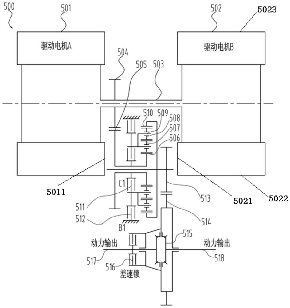
[0027] According to a preferred embodiment of the present invention, see figure 1 , provides a dual-motor two-speed electric drive axle structure 500, which is characterized in that it includes:

[0028] The first drive motor 501 and the second drive motor 502 are arranged at intervals from each other;

[0029] The two-speed reduction mechanism includes an input shaft 503, a first driving gear 504, a first driven gear 505, a first countershaft, a second countershaft, a clutch 511, a brake 512, a double-star planetary row, a second driving gear 513 and a second countershaft. Two driven gears 514, the two ends of the input shaft 503 are respectively connected to the first driving motor 501 and the second driving motor 502, the first driving gear 504 is connected to the input shaft 503, and the first driven gear 505 is connected to The first intermediate shaft meshes with the first driving gear 504. The double-star planetary row includes a sun gear 506, a first planetary gear 50...

Embodiment approach

[0033] According to yet another preferred embodiment of the present invention, the first drive motor 501 and the second drive motor 502 are arranged symmetrically at both ends of the input shaft 503 . Advantageously, the length of the input shaft 503 limits the arrangement range of the two-speed reduction mechanism, the differential case, and the differential lock 516 , thereby realizing an overall compact layout.

[0034] According to yet another preferred embodiment of the present invention, the first intermediate shaft and the second intermediate shaft are arranged on the boundary defined by the adjacent side surfaces 5011, 5021 and the upper and lower end surfaces 5023, 5022 of the first driving motor 501 and the second driving motor 502. There is a predetermined distance between the first drive motor 501 and the second drive motor 502 in the space and between the two ends. It can be understood that the first intermediate shaft and the second intermediate shaft are located...


PUM


Abstract

The invention provides a double-motor two-gear electric drive axle structure which comprises a first drive motor and a second drive motor which are arranged in a spaced mode; a two-gear speed reducing mechanism which comprises an input shaft, a first driving gear, a first driven gear, a first intermediate shaft, a second intermediate shaft, a clutch, a brake, a double-star planet row, a second driving gear and a second driven gear; and a differential. According to the structure, the double-motor and parallel-shaft structure arrangement is adopted, the axial length of the output shaft is reduced, whole-vehicle arrangement of an independently-suspended vehicle is facilitated, high and low gears are achieved on a double-star planet row after the motors are subjected to first-stage speed reduction, the transmission ratio is reduced, and the economical efficiency and gear shifting comfort of the vehicle are improved.

Description

technical field [0001] The invention relates to the field of transmission of new energy vehicles, in particular to a double-motor two-speed electric drive axle structure. Background technique [0002] Electric-driven new energy vehicles are the world trend and future development direction. As a common transmission mechanism, the drive axle is widely used in the field of mechanical and vehicle transmission. In order to adapt to the development of new energy vehicle technology, an electric drive axle driven by a drive motor has appeared. Most of the electric drive axles on the market are in one gear. The electric drive axle has high energy consumption and cannot meet the more complex transmission requirements. The two-speed electric drive axle on the market has a complex structure and does not get rid of the structural constraints of the bevel gear main reducer. The built-in structure is not compact enough, the cost is high, and the volume Large, difficult to arrange in a lim...

Claims


Application Information

Patent Timeline
Patent Type & Authority Applications(China)
IPC IPC(8): B60K1/02B60K17/04B60K17/16
CPCB60K1/02B60K17/046B60K17/165
Inventor 李吉元王明成石彦辉冯光军李晨魏建飞李培浩钱鹏虎
Owner 江苏华永复合材料有限公司
Learn More