
Automatic mechanical part stamping equipment

A technology for stamping equipment and mechanical parts, applied in the field of stamping equipment for automated mechanical parts, can solve problems such as single function, and achieve the effect of easy removal

Pending Publication Date: 2022-01-14
陈淑清
View PDF1 Cites 2 Cited by
  • Summary
  • Abstract
  • Description
  • Claims
  • Application Information

AI Technical Summary

Problems solved by technology

[0005] In order to overcome the shortcomings of the existing device with single function and excessive reliance on manual assistance, the technical problem to be solved is: to provide a multi-functional automatic mechanical parts stamping equipment that reduces manual operations

Method used


Image

  • Automatic mechanical part stamping equipment
  • Automatic mechanical part stamping equipment
  • Automatic mechanical part stamping equipment

Examples


Embodiment 1

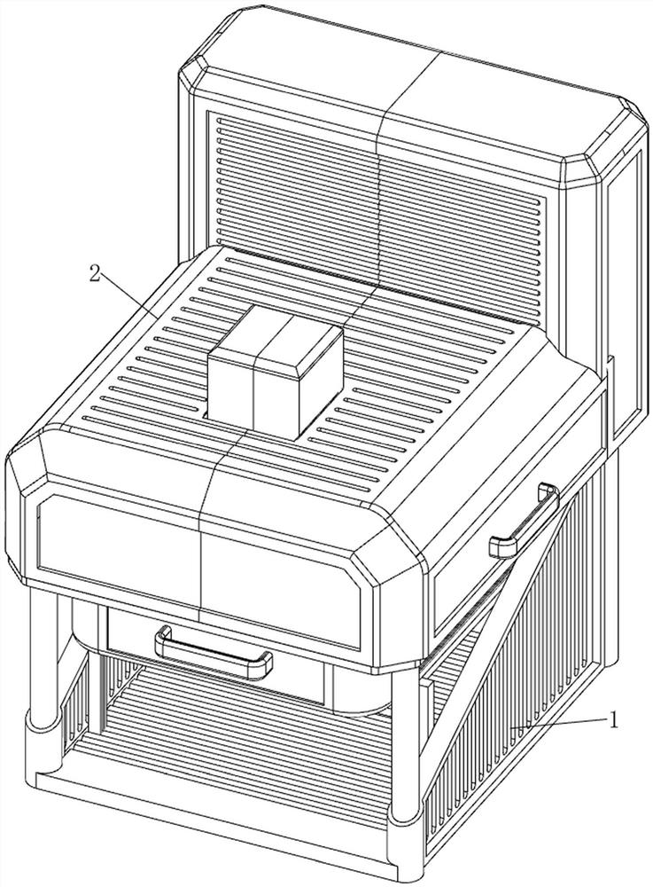
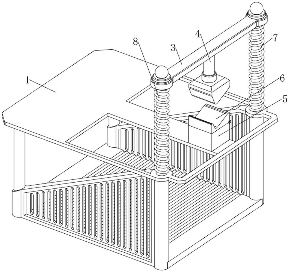
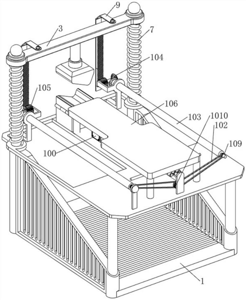
[0037] A stamping equipment for automated mechanical parts, such as Figure 1-18 As shown, it includes a base 1, a first shell 2, a first connecting rod 3, an upper mold 4, a stamping table 5, a lower mold 6, a first slide bar 7, a first spring 8, a rack 9, a transmission mechanism 10 and The push mechanism 11, the base 1 is fixedly connected with the first shell 2, the left and right sides of the rear side of the base 1 are fixedly connected with the first slide bar 7, and the top of the first slide bar 7 is jointly slidably connected with the first connecting rod 3, the first The first spring 8 is set on the sliding rod 7, the bottom of the first spring 8 is fixedly connected with the base 1, the top of the first spring 8 is fixedly connected with the first connecting rod 3, and the middle of the bottom of the first connecting rod 3 is fixedly connected with the upper mold 4. The middle of the rear side of the base 1 is fixedly connected with a stamping table 5, the top of t...


PUM


Abstract

The invention relates to part stamping equipment, in particular to automatic mechanical part stamping equipment. The technical problem to be solved is to provide the automatic mechanical part stamping equipment which is multifunctional and reduces manual operation. According to the technical scheme, the automatic mechanical part stamping equipment comprises a base, a first shell, a first connecting rod and first sliding rods, wherein the first shell is fixedly connected to the base, the first sliding rods are fixedly connected to the two sides of the base, and the first sliding rods are jointly connected with the first connecting rod in a sliding mode. Stamped finished parts are placed in a collecting frame, under the gravity effect of the finished parts, a collecting frame is driven to move downwards, the collecting frame drives a second supporting plate to move downwards, then first wedge-shaped blocks are driven to move downwards, so that fourth springs are compressed, and the effect that the finished parts in the collecting frame can be taken out more conveniently is achieved.

Description

technical field [0001] The invention relates to a part punching equipment, in particular to an automatic mechanical part punching device. Background technique [0002] The use of automated machinery and equipment for production will undoubtedly reduce the risk of factory annual production cost fluctuations. Therefore, cost-effective automated machinery and equipment have become a hot resource for factories, especially in the field of parts stamping. The desire for automated mechanical parts stamping equipment is even more obvious. [0003] Patent application CN112692137A, published on April 23, 2021, discloses a stamping processing workbench for metal parts, including a shell, and support columns are fixedly installed on the left and right sides of the upper surface of the shell, and the two The same support plate is fixedly installed on the upper surface of the support column, and the electric push rod is fixedly installed on the lower surface of the support plate, and a re...

Claims


Application Information

Patent Timeline
Patent Type & Authority Applications(China)
IPC IPC(8): B21D43/20B21D22/02B08B1/02B08B1/20
CPCB21D43/20B21D22/02B08B1/20B08B1/30B08B1/12
Inventor 陈淑清
Owner 陈淑清
Learn More