Camera shooting system
A camera system and image-side technology, applied in the field of camera systems, can solve problems such as complex shooting environment, imaging limitations, and difficulty in obtaining clear images, and achieve the effects of improving shooting effects, reducing aberrations, and increasing the clear aperture
- Summary
- Abstract
- Description
- Claims
- Application Information
AI Technical Summary
Problems solved by technology
Method used
Image

Examples
specific Embodiment 1
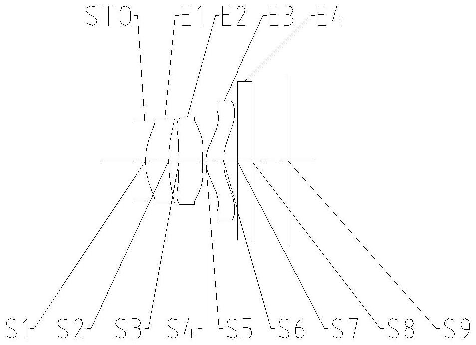
[0073] figure 1 It is a schematic diagram of the structure of the lens group in Embodiment 1 of the imaging system of the present invention. The imaging system includes in sequence from the object side to the image side along the optical axis: a diaphragm STO, a first lens E1, a second lens E2, a third lens E3, a filter Slice E4 and imaging surface S9.
[0074] The first lens E1 has positive refractive power, its object side S1 is convex, and its image side S2 is concave. The second lens E2 has negative refractive power, its object side S3 is concave, and its image side S4 is concave. The third lens E3 has positive refractive power, its object side S5 is convex, and its image side S6 is concave. The filter E4 has an object side S7 and an image side S8. The light from the object passes through each of the surfaces S1 to S8 in sequence and is finally imaged on the imaging plane S9.
[0075] As shown in Table 1, it is a table of basic parameters of the camera system in Embodi...
Embodiment 1
[0081] The camera system in embodiment 1 satisfies:
[0082] f×tan(semi-fov)=1.22; wherein, f is the effective focal length of the camera system, and semi-fov is half of the maximum field of view of the camera system.
[0083] DT12 / ImgH=0.49; wherein, DT12 is the effective semi-diameter of the image side of the first lens, and Imgh is half of the diagonal length of the effective pixel area on the imaging surface.
[0084]f23 / f=1.28; wherein, f23 is the combined focal length of the second lens and the third lens, and f is the effective focal length of the camera system.
[0085] f1 / f=2.56; wherein, f1 is the effective focal length of the first lens, and f is the effective focal length of the camera system.
[0086] EPD / f3=1.38; wherein, EPD is the entrance pupil diameter of the camera system, and f3 is the effective focal length of the third lens.
[0087] ET2 / CT2=0.63; wherein, ET2 is the edge thickness of the second lens, and CT2 is the center thickness of the second lens o...
specific Embodiment 2
[0097] image 3 It is a schematic diagram of the lens group structure of Embodiment 2 of the camera system of the present invention. The camera system includes in sequence from the object side to the image side along the optical axis: a diaphragm STO, a first lens E1, a second lens E2, a third lens E3, a filter Slice E4 and imaging surface S9.
[0098] The first lens E1 has positive refractive power, its object side S1 is convex, and its image side S2 is concave. The second lens E2 has negative refractive power, its object side S3 is concave, and its image side S4 is concave. The third lens E3 has positive refractive power, its object side S5 is convex, and its image side S6 is concave. The filter E4 has an object side S7 and an image side S8. The light from the object passes through each of the surfaces S1 to S8 in sequence and is finally imaged on the imaging plane S9.
[0099] As shown in Table 4, it is a table of basic parameters of the camera system of Embodiment 2, w...
PUM
 Abstract
Description
Claims
Application Information
 - R&D
- Intellectual Property
- Life Sciences
- Materials
- Tech Scout
- Unparalleled Data Quality
- Higher Quality Content
- 60% Fewer Hallucinations
Browse by: Latest US Patents, China's latest patents, Technical Efficacy Thesaurus, Application Domain, Technology Topic, Popular Technical Reports.
© 2025 PatSnap. All rights reserved.Legal|Privacy policy|Modern Slavery Act Transparency Statement|Sitemap|About US| Contact US: help@patsnap.com