
Movable spray cooling device and method for reducing near-field accumulated heat of tunnel face

A cooling device and mobile technology, applied in the direction of mobile frame, mine/tunnel ventilation, safety device, etc., can solve the problem of difficulty in effectively reducing the near-field accumulated heat of the tunnel face, affecting the life safety of workers, and inability to perform normal construction, etc. problems, to achieve the effect of improving the construction work environment, improving the cooling effect, and convenient material acquisition.

Pending Publication Date: 2022-01-11
中铁十四局集团建筑工程有限公司
View PDF0 Cites 0 Cited by
  • Summary
  • Abstract
  • Description
  • Claims
  • Application Information

AI Technical Summary

Problems solved by technology

In high temperature weather, the normal construction in the tunnel cannot be carried out, and it is in a state of shutdown for a long time; moreover, the temperature in the tunnel is too high to easily affect the life safety of workers
[0004] At present, the cooling measures in the tunnel include sprinkling water, placing ice cubes, and sending cold air, etc., but the temperature inside the tunnel is too high to effectively reduce the near-field heat accumulation of the tunnel face by using existing methods

Method used


Image

  • Movable spray cooling device and method for reducing near-field accumulated heat of tunnel face
  • Movable spray cooling device and method for reducing near-field accumulated heat of tunnel face
  • Movable spray cooling device and method for reducing near-field accumulated heat of tunnel face

Examples


Embodiment 1

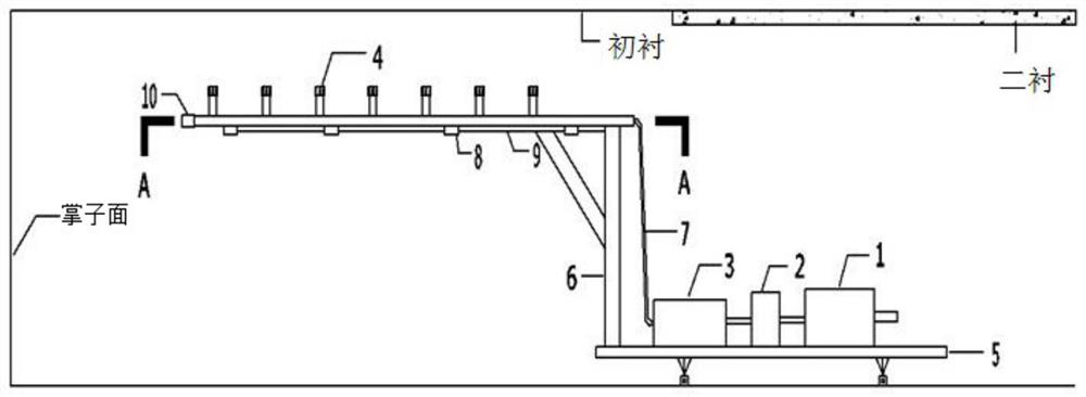
[0035] Such as figure 1 As shown, the mobile spray cooling device disclosed in this embodiment includes a water tank 1), an ice maker 2, a fog maker 3, a construction site flatbed 5 and a bracket.

[0036] The water tank 1, the ice maker 2 and the fog maker 3 are placed on the flatbed truck 5 on the construction site, and the bottom of the support is connected to the flatbed truck 5 on the construction site.

[0037] The bracket is equipped with a water-guiding high-pressure pipe network, and the water-guiding high-pressure pipe network is equipped with a plurality of atomizing nozzles 4 with water outlets facing upwards. The atomizing nozzles 4 communicate with the inside of the water-guiding high-pressure pipe network. The water in the water high-pressure pipe network is converted into an atomized state.

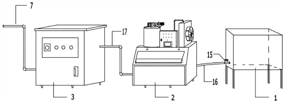
[0038] The storage bin 21 of the ice maker 2 has a cooling water flow channel 22 for the cooling water to pass through. The second pipeline 17 is connected to the water ...

Embodiment 2

[0055] Such as figure 2 As shown, in this embodiment, the middle parts of a plurality of cross bars 8 are connected with the longitudinal bars 9 to form a horizontal frame, and one side of the longitudinal bars 9 is fixedly connected with the upper end of the vertical bar 6 .

[0056] When the diameter of the high-pressure pipeline is reduced, a different-diameter joint should be used; a bushing should not be used at the elbow of the pipeline; when a bushing is required, a three-way connection should be used; a pipe with a nominal diameter greater than 50 mm should not use a live joint.

[0057] After the water pipe is laid through the fog machine 3, it is divided into four roads by the three-way 11 branch joint, and the end of each road is blocked with a terminal plug 10. The longitudinal length of each high-pressure pipe is 100-120 meters. The distance between the nozzles is 4 meters, and the distance between the nozzles is set to 1 meter on each road.

[0058] Straighten ...


PUM


Abstract

The invention relates to a movable spray cooling device and a method for reducing near-field accumulated heat of a tunnel face. The movable spray cooling device comprises an ice maker, a mist maker, a flat car, a support and a water guide high-pressure pipe network; the ice maker and the mist maker are arranged on the flat car, the bottom of the support is connected with the flat car, a water guide high-pressure pipe network is arranged on the support, a plurality of atomizing nozzles are arranged on the water guide high-pressure pipe network, and the atomizing nozzles communicates with the inside of the water guide high-pressure pipe network; a to-be-cooled water runner for allowing to-be-cooled water to pass through is arranged in an ice storage box of the ice maker, an inlet of the to-be-cooled water runner is exposed out of the ice maker, an outlet of the to-be-cooled water runner is connected with a water inlet of the mist maker, and a water outlet of the mist maker is connected with the water guide high-pressure pipe network. The mist maker and the ice maker are combined, the tunnel cooling effect can be improved, the cooling and dust falling functions are achieved, the arrangement of dust removing and cooling equipment does not need to be additionally arranged along with the tunnel excavation progress, and resources are saved; the cooling device has high practicability and can be popularized on a large scale.

Description

technical field [0001] The invention relates to the technical field of tunnel construction, in particular to a mobile spray cooling device and a method for reducing heat accumulation in the near field of a tunnel face. Background technique [0002] my country has a vast territory and complex terrain. Tunnel engineering construction is in a period of rapid development. The high geothermal heat brought about by the deepening of the buried depth of the tunnel and the heat generated during the tunnel construction cause the tunnel construction temperature to be too high, which has become an obstacle to the normal safety of the tunnel construction and One of the main reasons for reducing construction efficiency. A safe and good tunnel construction environment is an important condition to ensure the normal construction of the tunnel, improve the construction efficiency, and ensure the physical and mental safety of the construction personnel. [0003] During the construction process...

Claims


Application Information

Patent Timeline
Patent Type & Authority Applications(China)
IPC IPC(8): E21F3/00E21F5/04F16M3/00
CPCE21F3/00E21F5/04F16M3/00
Inventor 田动动冯霖冯子健周宝龙侯情祥谢飞鸿董建辉吴启红
Owner 中铁十四局集团建筑工程有限公司
Learn More