


Quick Research
Generate reliable direction feasibility study reports for your R&D in just a few steps.

Technical Q&A
Discover and master advanced knowledge NOW. Basics, ideas, possibilities, all at once.

Find Solutions
As an expert in R&D theories, this can generate solutions to your technical problems instantly.

Evaluate Feasibility
Analyze your overall solution with one click, know your potential R&D risks in advance.

Monitor Landscape
Get weekly tech updates, stay abreast of the latest tech innovations and key insights.
Bag type dust removal device for flue gas treatment
A bag-type dust removal and flue gas treatment technology, which is used in combination devices, separation methods, and dispersed particle separation, etc., can solve the problems of dust-removing bags being easily stuck by dust, difficult to remove dust from dust-removing bags, and clogging.
- Summary
- Abstract
- Description
- Claims
- Application Information
AI Technical Summary
Problems solved by technology
Method used
Image

Examples
Embodiment 1
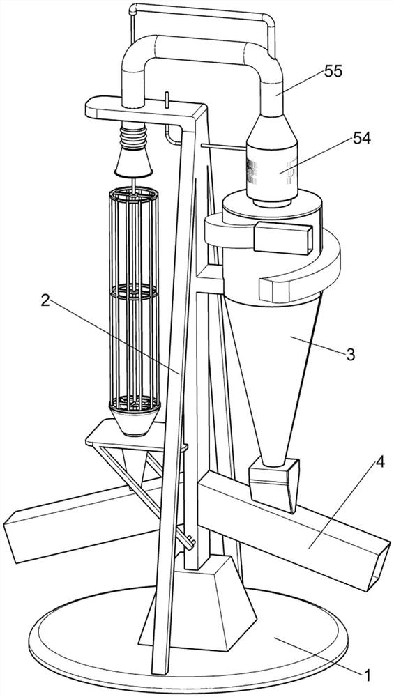
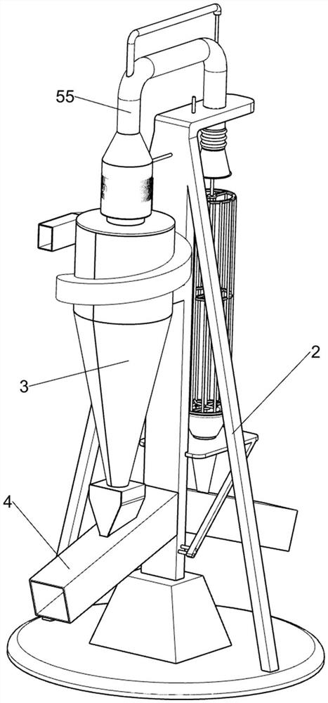
[0041] A bag type dust removal device for flue gas treatment, such as figure 1 , figure 2 , image 3 , Figure 4 , Figure 5 , Figure 6 , Figure 7 , Figure 8 , Figure 9 , Figure 10 , Figure 11 , Figure 13As shown, it includes a chassis 1, a fixed support 2, a preliminary filter cartridge 3, a blanking frame 4, a preliminary filter assembly 5, a bag-type dust removal assembly 6, and a dust bag scraping assembly 7. The top surface of the chassis 1 is fixedly installed with a fixed support Seat 2, the right side of the middle part of the fixed support 2 is fixed with a preliminary filter cartridge 3, the preliminary filter cartridge 3 is used to separate the particles in the flue gas, the bottom of the fixed support 2 is symmetrically arranged with a blanking frame 4, and the preliminary filter assembly 5 is set On the preliminary filter cartridge 3, the preliminary filter assembly 5 is used for preliminary filtering of the flue gas, and the left side of the fix...
Embodiment 2
[0048] On the basis of Example 1, such as Figure 11 , Figure 12 As shown, a filter heating assembly 8 is also included. The filter heating assembly 8 is positioned in the filter cone 54. The filter heating assembly 8 is used to filter the flue gas and remove moisture. The filter heating assembly 8 includes a fixed ring frame 81 and a curved shaped filter heating tank 82, the filter cone 54 is fixed with a fixed ring frame 81, the bottom surface of the fixed ring frame 81 is provided with a curved filter heating tank 82, the curved filter heating tank 82 will guide and heat the flue gas .
[0049] When the flue gas enters the filtering cone 54, the curved filtering heating tank 82 will guide the flue gas, and the dust in the flue gas will stick to the curved filtering heating tank 82 to achieve the purpose of filtering the flue gas. At the same time, the curved filter heating tank 82 will generate heat and heat the flue gas, so as to avoid excessive moisture in the flue gas...
Embodiment 3
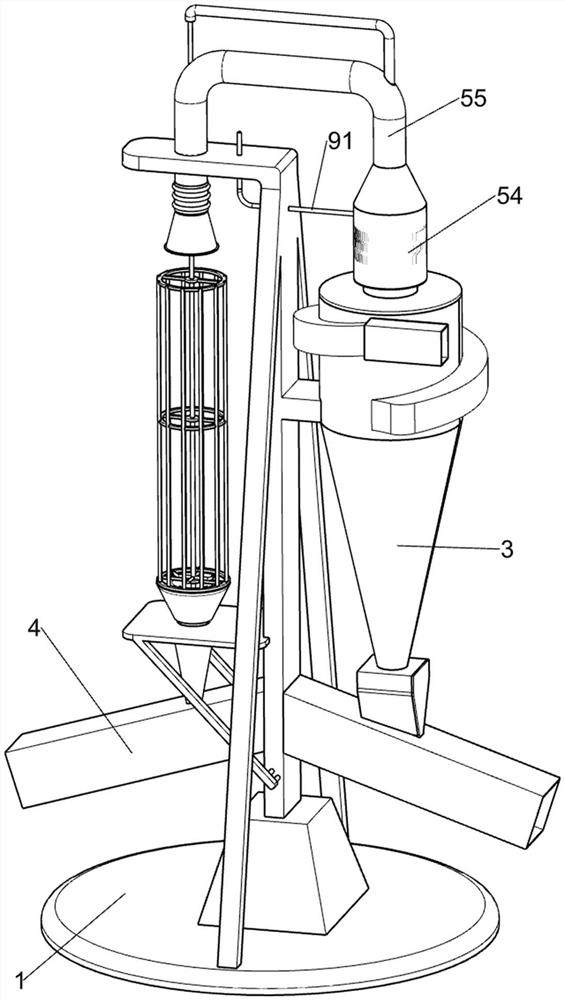
[0051] On the basis of Example 2, such as Figure 11 As shown, it also includes a filter scouring assembly 9, the filter cone 54 is provided with a filter scouring assembly 9, the filter scouring assembly 9 is used to clean the curved filter heating tank 82, and the filter scouring assembly 9 includes Water inlet pipe 91 and annular water outlet pipe 92, filter cone 54 middle part is fixedly connected with water inlet pipe 91, water inlet pipe 91 runs through fixed support 2, and the right end of water inlet pipe 91 is connected with annular water outlet pipe 92, and annular water outlet pipe 92 is used for spraying water The curved filter heating tank 82 is cleaned, and the annular water outlet pipe 92 is located in the filter cone 54 .
[0052] The water inlet pipe 91 is connected with the water delivery pipe. When the curved filter heating tank 82 needs to be cleaned after the dust removal in the later stage, the staff controls the water delivery pipe to pour water towards ...
PUM
 Abstract
Description
Claims
Application Information
 - R&D Engineer
- R&D Manager
- IP Professional
- Industry Leading Data Capabilities
- Powerful AI technology
- Patent DNA Extraction
Browse by: Latest US Patents, China's latest patents, Technical Efficacy Thesaurus, Application Domain, Technology Topic, Popular Technical Reports.
© 2024 PatSnap. All rights reserved.Legal|Privacy policy|Modern Slavery Act Transparency Statement|Sitemap|About US| Contact US: help@patsnap.com