Multi-path relay switch module
A technology of relay switch and isolating switch, which is applied in the direction of relay, electromagnetic relay, detailed information of electromagnetic relay, etc., can solve the problem of easy heating of PCB board, achieve the effect of avoiding temperature rise, speeding up the flow of gas, and increasing the area
- Summary
- Abstract
- Description
- Claims
- Application Information
AI Technical Summary
Problems solved by technology
Method used
Image

Examples
Embodiment 1
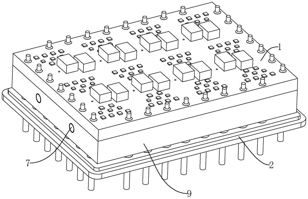
[0037] refer to figure 1 A multi-channel relay switch module includes a PCB board 1 and a copper clad laminate 2 arranged below the PCB board 1, electrical components are arranged on the PCB board 1, the PCB board 1 and the copper clad laminate 2 are both rectangular, and the PCB board 1 and the A plurality of metal connecting columns are arranged between the copper clad laminates 2 , the connecting columns are arranged vertically, the upper ends of the connecting columns are welded to the PCB 1 , and the lower ends of the connecting columns are welded to the copper clad laminate 2 .
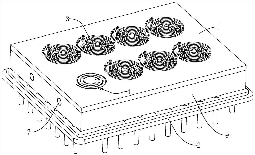
[0038] refer to figure 1 , figure 2 and image 3 , a plurality of planar coils 3 are arranged inside the PCB board 1, and the plurality of planar coils 3 are distributed in an equidistant array along the length direction and the width direction of the PCB board 1. In the embodiment of the present application, the number of planar coils 3 is 8, 8 The four planar coils 3 are distributed in two...
Embodiment 2
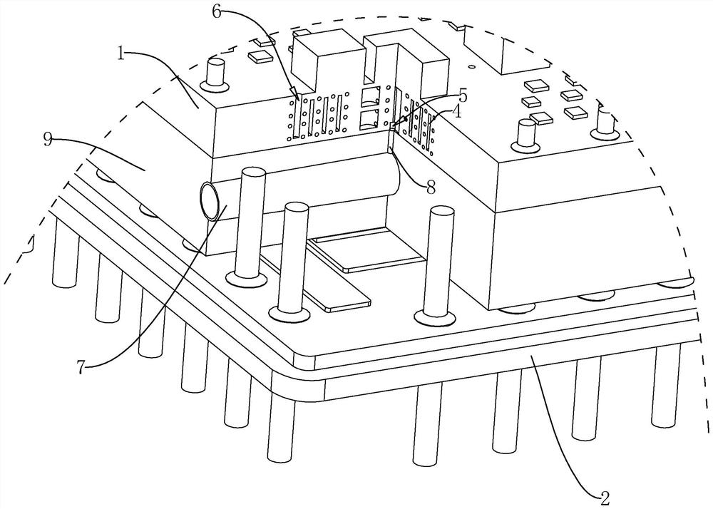
[0045] refer to Figure 4 The difference between this embodiment and Embodiment 1 is that the air flow channel 4 is located between two adjacent coils of the planar coil 3, and the air flow channel 4 is distributed along the spiral direction of the planar coil 3 in a serpentine manner, inside the PCB board 1 The serpentine air flow channel 4 increases the area of the air flow channel 4 flowing through the inside of the PCB board 1, and the serpentine air flow channel 4 is closer to the heating position of the planar coil 3, so as to better protect the PCB board 1 to cool down.
[0046] The implementation principle of Embodiment 2 is: during the working process of the relay switch module, the gas with a lower temperature introduced into the air guide tube 7 can enter the serpentine spiral air flow channel 4 through the air inlet pipe 8, and In the process of circulating from the head end of the air flow channel 4 to the end of the air flow channel 4, the heat dissipation and...
Embodiment 3
[0048] refer to Figure 5 , The difference between this embodiment and Embodiment 1 is that the air flow channel 4 and the planar coil 3 are nested with each other, and a plurality of air channels are uniformly arranged in the spiral direction of the air flow channel 4 and from the beginning to the end. cavity 41, the gas cavity 41 is set inside the PCB board 1, and the gas cavity 41 is arc-shaped and has a rectangular cross section. The two sides of the gas cavity 41 are closer to the planar coil 3. When the gas flows into the gas cavity 41, A certain amount of gas with a relatively low temperature is stored inside the gas chamber 41 , and the gas can circulate inside the gas chamber 41 during the flow of the gas in the air flow channel 4 , and then flow into the next gas chamber through the air flow channel 4 Inside 41, the gas chamber 41 provided can cool down the PCB board 1 in a large range, and increase the cooling speed of the PCB board 1 .
[0049] The implementation ...
PUM
 Abstract
Description
Claims
Application Information
 - Generate Ideas
- Intellectual Property
- Life Sciences
- Materials
- Tech Scout
- Unparalleled Data Quality
- Higher Quality Content
- 60% Fewer Hallucinations
Browse by: Latest US Patents, China's latest patents, Technical Efficacy Thesaurus, Application Domain, Technology Topic, Popular Technical Reports.
© 2025 PatSnap. All rights reserved.Legal|Privacy policy|Modern Slavery Act Transparency Statement|Sitemap|About US| Contact US: help@patsnap.com