
Method for calculating circulation path of circulating airflow in straight-flow type vertical shaft structure

A technology of circulation path and internal circulation, applied in the direction of calculation, computer-aided design, drainage structures, etc., can solve the problems of reducing efficiency and ideal effect, so as to reduce the construction and use cost, reduce the suction effect, and improve the construction efficiency and use. effect of effect

Pending Publication Date: 2022-01-07
LANZHOU UNIVERSITY OF TECHNOLOGY
View PDF1 Cites 0 Cited by
  • Summary
  • Abstract
  • Description
  • Claims
  • Application Information

AI Technical Summary

Problems solved by technology

Although the above-mentioned shaft structure can reduce the suction of the shaft to a certain extent, there is no specific algorithm for the upper orifice of this structure to guide the specific location of the opening, which greatly reduces its efficiency, so the effect is not very ideal

Method used


Image

  • Method for calculating circulation path of circulating airflow in straight-flow type vertical shaft structure
  • Method for calculating circulation path of circulating airflow in straight-flow type vertical shaft structure
  • Method for calculating circulation path of circulating airflow in straight-flow type vertical shaft structure

Examples


Embodiment 1

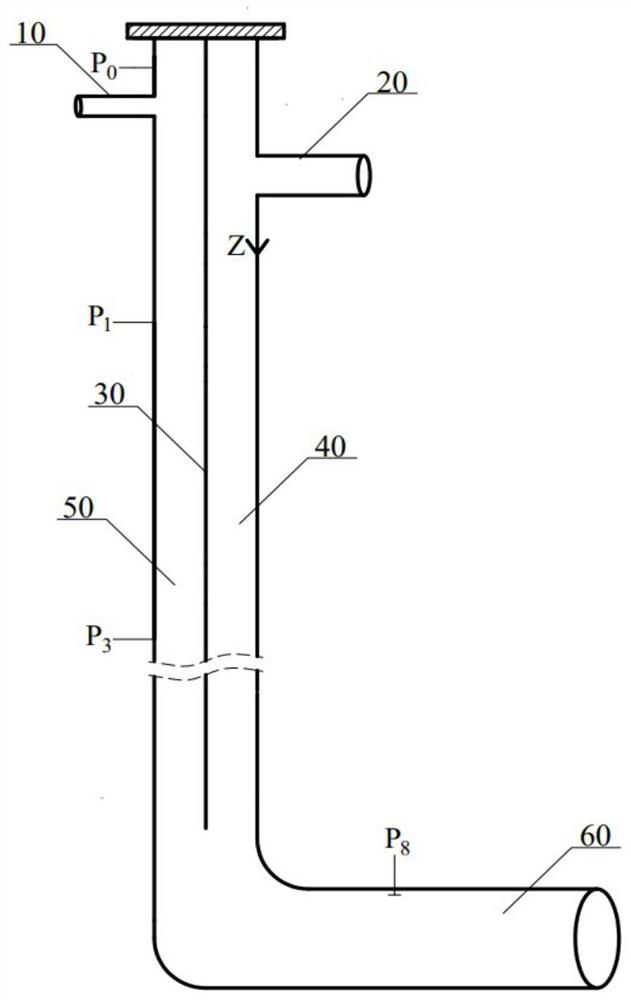
[0104] established as figure 1 As shown, the end of the water inlet pipe 20 is taken as the origin (the position of the water tongue), and the downward is the coordinate axis in the positive direction; The equivalent diameter D s Equivalent diameter D with the trachea 50 c The same is 0.265m, the diameter of the intake pipe is 10 D I The diameter of the outlet pipe 60 is 0.38m, and the diameter of the inlet pipe 20 is 0.19m. The shaft top is sealed, gas can only enter from the inlet pipe 10, water flows through the water inlet pipe 20 to the wet pipe 40, and then flows out from the outlet pipe 60, which communicates with the atmosphere.

[0105] Correspondingly, P 0 As the air pressure at the intake pipe, the air pressure at Z=-0.64m can be selected, that is, the air pressure at 0.64m above the water tongue.

[0106] It should be understood that the air pressure at the intake pipe is the air pressure above the water tongue and around the air intake pipe. In practical appl...


PUM


Abstract

The invention provides a method for calculating the circulation path of circulating airflow in a straight-flow type vertical shaft structure, a vertical partition plate is arranged at the radial position of a vertical shaft with a sealed top end, one end of the vertical partition plate is connected with the top end of the vertical shaft, so that the vertical shaft is divided into a wet pipe section and an air pipe section, the wet pipe section is connected with a water inlet pipe, and the air pipe section is connected with a breather pipe; the air pressure distribution of each section in a wet pipe and the air pressure distribution in an air pipe under a certain incoming water amount are respectively calculated, the air pressure intersection point of the wet pipe section and the air pipe section, namely the air pressure critical value, is obtained, and the position of the air pressure critical value is the critical position; when one end of a partition plate is placed at the critical position or is arranged at any position between the critical position and the top end of the vertical shaft, the air flow in the vertical shaft can form internal circulation air flow. By means of the method, the specific placement position of the partition plate can be obtained when the internal circulation airflow is formed, the downstream of a blow-off pipeline is effectively prevented from being pressurized, and theoretical guidance is provided for structural optimization and design of the vertical shaft.

Description

technical field [0001] The invention relates to the technical field of municipal engineering sewage pipelines, in particular to a method for calculating the circulating air flow path in a straight-through shaft structure. Background technique [0002] As one of the most important falling water structures in the urban drainage system, the shaft is mainly used to guide the sewage in the many drainage pipes close to the surface to the buried deep underground main drainage channel through the shaft. A series of changes will occur during the free fall of the water flow from the shaft. The most important change is that the initial complete and continuous flake water flow gradually collides, breaks and decomposes after falling to a certain height. When the water flow approaches the bottom of the shaft, most of it is in the shape of water droplets. . In this case, it is often accompanied by the phenomenon of shaft suction, which causes the pressure gradient in the shaft to be too l...

Claims


Application Information

Patent Timeline
Patent Type & Authority Applications(China)
IPC IPC(8): G06F30/20E03F5/04G06F113/14
CPCG06F30/20E03F5/04G06F2113/14
Inventor 魏佳芳芦三强赵文举龙丽丽马亮军
Owner LANZHOU UNIVERSITY OF TECHNOLOGY
Learn More