
Sensor for monitoring outdoor air humidity

An outdoor air and sensor technology, applied in the field of unmanned aerial vehicles, can solve the problems of increased measurement error and reduced reliability of air humidity information, and achieves the effect of convenient maintenance and replacement, and flexible disassembly and assembly.

Active Publication Date: 2022-01-07
西安杰出科技有限公司 +1
View PDF11 Cites 2 Cited by
  • Summary
  • Abstract
  • Description
  • Claims
  • Application Information

AI Technical Summary

Problems solved by technology

[0002] With the rapid development of drone technology in recent years, people have applied drone technology to various fields of life. In order to ensure people's normal travel, they must always pay attention to factors such as air humidity and temperature. It can remind people to make corresponding preparations when traveling. The traditional air humidity sensor cannot reach the high altitude, but the sensor mounted on the drone can detect the air humidity above the plants, so as to judge the change of the air humidity at high altitude. Use this to judge the subsequent impact of high-altitude air humidity on low-altitude
[0003] Existing sensors used to monitor outdoor air humidity often leak the sensing unit of the sensor during use, so that the sensing unit is always in contact with the air, and the air humidity at different heights is different during the ascent of the drone. Similarly, the sensor is always in contact with the air, and the collected values ​​are constantly changing. After the sensor rises to the specified height, the influence of low-altitude air may increase the measurement error, so that the air humidity information collected by people Reduced credibility

Method used


Image

  • Sensor for monitoring outdoor air humidity
  • Sensor for monitoring outdoor air humidity
  • Sensor for monitoring outdoor air humidity

Examples


Embodiment Construction

[0038] In order to make the objects and advantages of the present invention clearer, the present invention will be specifically described below in conjunction with examples. It should be understood that the following words are only used to describe one or several specific implementation modes of the present invention, and do not strictly limit the protection scope of the specific claims of the present invention.

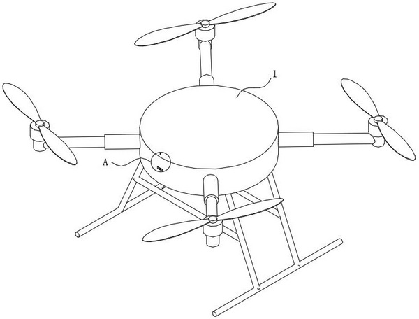
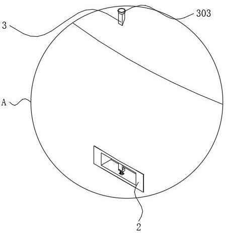
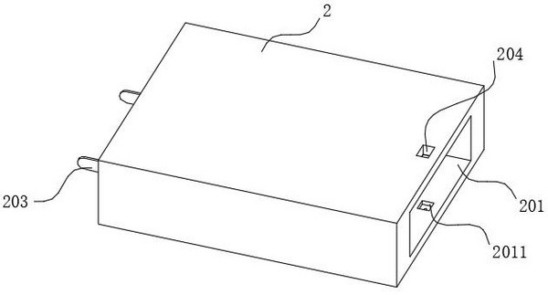
[0039] Such as figure 1 and figure 2 As shown, a sensor for monitoring outdoor air humidity includes a drone body 1, a windshield mechanism, a transmission mechanism and a positioning assembly, and a sensor body 2 is installed inside the drone body 1 (the sensor body 2 is a humidity sensor ), the sensor body 2 is used to monitor the outdoor air humidity, the windshield mechanism is arranged inside the sensor body 2, the transmission mechanism is arranged inside the sensor body 2, and the positioning component is arranged below the transmission mechanism.

[0040] ...


PUM


Abstract

The invention belongs to the technical field of unmanned aerial vehicles, and particularly relates to a sensor for monitoring the outdoor air humidity. The sensor comprises an unmanned aerial vehicle body, a wind shielding mechanism, a transmission mechanism and a positioning assembly. A sensor body is installed in the unmanned aerial vehicle body, the wind shielding mechanism is used for sealing a port of the sensor body, the transmission mechanism is used for driving the wind shielding mechanism to move, and the positioning assembly is used for fixing the sensor body in the unmanned aerial vehicle body. When the unmanned aerial vehicle body ascends, the transmission mechanism drives the wind shielding mechanism to seal the port of the sensor body, and the wind shielding mechanism resets and gradually opens the port of the sensor body along with the balance of the unmanned aerial vehicle body in the air. After the unmanned aerial vehicle body reaches the required height and is balanced, the wind shielding mechanism automatically relieves blocking of the sensor body, and then the interior of the sensor body can be in direct contact with air at the required height.

Description

technical field [0001] The invention belongs to the technical field of drones, and in particular relates to a sensor for monitoring outdoor air humidity. Background technique [0002] With the rapid development of drone technology in recent years, people have applied drone technology to various fields of life. In order to ensure people's normal travel, they must always pay attention to factors such as air humidity and temperature. It can remind people to make corresponding preparations when traveling. The traditional air humidity sensor cannot reach the high altitude, but the sensor mounted on the drone can detect the air humidity above the plants, so as to judge the change of the air humidity at high altitude. This is used to judge the subsequent impact of high-altitude air humidity on low-altitude. [0003] Existing sensors used to monitor outdoor air humidity often leak the sensing unit of the sensor during use, so that the sensing unit is always in contact with the air,...

Claims


Application Information

Patent Timeline
Patent Type & Authority Applications(China)
IPC IPC(8): G01N33/00B64C39/02B64D47/00
CPCG01N33/0009B64C39/02B64D47/00
Inventor 陈杰王飞虎
Owner 西安杰出科技有限公司
Learn More