
Ultrasonic nondestructive testing device and method for T-shaped composite structure and R-region detection method and device

A technology of composite structure and detection method, which is applied in the direction of measuring device, analysis of solids by using sound wave/ultrasonic wave/infrasonic wave, material analysis by using sound wave/ultrasonic wave/infrasonic wave, etc. It can solve the problems of high measurement cost, poor detection effect and poor acoustic coupling effect And other problems, to achieve the effect of improving detection accuracy, improving stability and improving work efficiency

Active Publication Date: 2022-01-07
国营芜湖机械厂 +1
View PDF43 Cites 3 Cited by
  • Summary
  • Abstract
  • Description
  • Claims
  • Application Information

AI Technical Summary

Problems solved by technology

[0007] The problem to be solved by this application is: the existing method is not good for the detection of the R zone of the T-shaped composite structure, and there is a problem that the detection effect is poor due to the poor acoustic coupling effect, and the detection needs for different layers of the T-shaped composite structure Different devices are used for detection, the measurement process is complicated, and the measurement cost is high

Method used


Image

  • Ultrasonic nondestructive testing device and method for T-shaped composite structure and R-region detection method and device
  • Ultrasonic nondestructive testing device and method for T-shaped composite structure and R-region detection method and device
  • Ultrasonic nondestructive testing device and method for T-shaped composite structure and R-region detection method and device

Examples


Embodiment approach 1

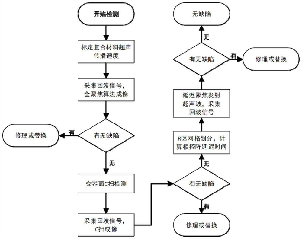
[0089] Embodiment 1. This embodiment proposes a method for detecting the back side of defects in the R region of a T-shaped composite structure, which is characterized in that the method is:

[0090] Ultrasonic signals are emitted from the back of the R zone and outside the top composite material layer, and echo signals are collected, and whether there is a defect in the R zone to be detected is obtained according to the echo signal, and the coordinates of the defect position are determined.

Embodiment approach 2

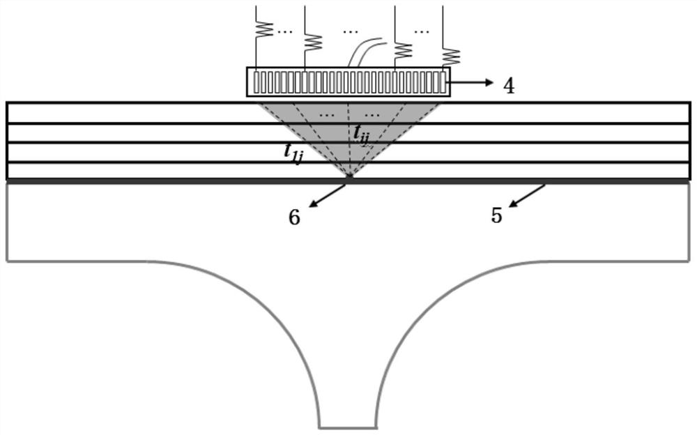
[0091] Embodiment 2. Combination figure 1 and 4 This embodiment is described. This embodiment is a further limitation of the back detection method for R-zone defects of a T-shaped composite structure proposed in Embodiment 1. The method is as follows:

[0092] Calibrate the propagation speed of ultrasonic waves in all directions inside the top composite material to be tested;

[0093] The target area to be detected is divided into grids to obtain multiple grid points, and each grid point is detected from the back of the R area one by one with an ultrasonic phased array:

[0094] For the i-th array element of the ultrasonic phased array, according to the Fermat principle, the coordinates of the ultrasonic phased array are obtained as (x i ,z i ) The i-th array element transmits the ultrasonic wave through two layers of media to the propagation time T of the focal point P i :

[0095]

[0096] Among them, c 1 Indicates the ultrasonic propagation velocity of the first l...

Embodiment approach 3

[0103] Embodiment 3. This embodiment proposes a rear ultrasonic nondestructive testing device for defects in the R zone of a T-shaped composite structure. The device includes:

[0104] propagation time T i The acquisition module is used to obtain the coordinates of the phased array according to Fermat's principle as (x i ,z i ) from the upper part of the T-shaped composite structure for the i-th array element to transmit ultrasonic waves through two layers of media to reach the focal point P with propagation time T i :

[0105]

[0106] In the formula, c 1 Indicates the ultrasonic propagation speed of the first layer of medium, c 2 Indicates the ultrasonic propagation velocity of the second layer medium, (x s ,z s ) represents the incident point coordinates of the ultrasonic wave from the first layer of medium to the second layer of medium, (x 0 ,z 0 ) represents the coordinates of the focal point of emitting ultrasonic waves, H represents the thickness of the top l...


PUM


Abstract

The invention discloses an ultrasonic non-destructive testing device and method for a T-shaped composite structure and an R-region testing method and device, and relates to the field of non-destructive testing. An existing T-shaped composite structure is low in defect detection precision, and no method capable of accurately detecting defects of an R region exists. In order to solve the problems, the technical scheme adopted by the invention comprises the following steps: calibrating the propagation speed of ultrasonic waves in all directions in a tested composite material, and collecting reflection echoes generated when the ultrasonic waves are propagated in the material for imaging; obtaining the reflection echo intensity at the interface of the two materials, and carrying out imaging; detecting from the back surface of the R region; and performing judging according to a detection result and an imaging result. In-service ultrasonic nondestructive testing is carried out on the T-shaped composite structure by adopting a layer-by-layer scanning mode, the defect detection precision of the T-shaped composite structure is effectively improved, and meanwhile, the difficulty of R-region detection is simplified by utilizing a method of emitting focused ultrasonic waves from the back surface of the R region. The method and device can be applied to the detection work of the T-shaped composite structure in the aerospace field.

Description

technical field [0001] This application relates to the technical field of non-destructive testing, in particular to the technical field of non-destructive testing of T-shaped composite structures. Background technique [0002] A T-shaped composite structure formed by bonding composite materials and metal materials is widely used in the aerospace field. For composite materials, it is easy to produce delamination defects inside, which will seriously affect the bearing capacity and service life of structural parts. There is bonding at the interface of the two materials, and it is also prone to debonding defects, which will affect the original performance of the structure. In addition to the above two defects, the R angle is common in the T-shaped structure. Due to the limitation of the space size and shape, the radius of curvature of the R angle area is generally small, the cross-sectional geometry of the part changes suddenly, and the local stress is much greater than the nomi...

Claims


Application Information

Patent Timeline
IPC IPC(8): G01N29/07G01N29/44
CPCG01N29/07G01N29/4472G01N2291/0231
Inventor 阚艳范鑫张平程宗辉朱萌史维佳李佳鑫
Owner 国营芜湖机械厂
Learn More