
Novel load element model considering power electronic influence

A component model, power electronics technology, applied in the field of power system, can solve problems such as increasing the complexity of power grid operation, increasing the diversity and identification difficulty of load models, and inability to consider inertial index.

Pending Publication Date: 2022-01-04
SOUTHEAST UNIV +1
View PDF3 Cites 0 Cited by
  • Summary
  • Abstract
  • Description
  • Claims
  • Application Information

AI Technical Summary

Problems solved by technology

Different from traditional grid load components, new energy grid-connected and controllable power equipment with power electronics as the interface are widely used in the grid. The physical characteristics of load components are shielded by power electronics interface circuits, such as through power electronics inverters. Grid-connected wind turbines cannot consider their inertial index on the grid side
In addition, with the help of high-performance control logic implemented by power electronic devices, pulse width modulation technology, and control algorithms, the load power factor of the power electronic interface can be approximated to 1. This index has a significant effect on reducing energy consumption, but redefining the load electrical characteristics, which further increases the diversity of load models and the difficulty of identification, increases the complexity of power grid operation, and puts forward new requirements for dispatching systems and staff

Method used


Image

  • Novel load element model considering power electronic influence
  • Novel load element model considering power electronic influence
  • Novel load element model considering power electronic influence

Examples


Embodiment Construction

[0035] The following will clearly and completely describe the technical solutions in the embodiments of the present invention with reference to the accompanying drawings in the embodiments of the present invention. Obviously, the described embodiments are only some, not all, embodiments of the present invention. Based on the embodiments of the present invention, all other embodiments obtained by persons of ordinary skill in the art without creative efforts fall within the protection scope of the present invention.

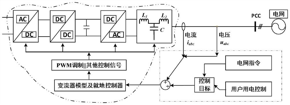
[0036] A new load element model considering power electronic converters and physical mechanisms, such as figure 1 , figure 2 As shown, the load element model includes a model based on the physical mechanism of the load element and a converter transformation model.

[0037] The converter conversion model includes the grid-side model of the converter, the DC-to-DC model of the converter and the load-side model of the converter, the grid-side model of the converter,...


PUM


Abstract

The invention discloses a novel load element model considering power electronic influence, the load element model comprises a load element physical mechanism-based model and a converter transformation model, and the converter transformation model comprises a power grid side model of a converter, a DC-DC model of the converter and a load side model of the converter. The power grid side model of the converter, the DC-DC model of the converter and the load side model of the converter are connected in series. According to the load element model, a power electronic interface circuit model and a power load element physical mechanism are fused, the characteristics of a power electronic converter can be embodied, the characteristics of power electronics can also be embodied, the power electronic converter is converted into a converter power grid side port equivalent circuit through a two-port network equivalent model, and, for a converter conversion matrix consists of a port equivalent circuit at the load side of the converter and the like, so that the behavior characteristics of the novel load element can be described more accurately.

Description

technical field [0001] The invention relates to the field of power systems, in particular to a novel load element model considering the influence of power electronics. Background technique [0002] It is necessary to build a clean, low-carbon, safe and efficient energy system, control the total amount of fossil energy, focus on improving utilization efficiency, implement renewable energy substitution actions, deepen the reform of the power system, and build a new power system with new energy as the main body. "Elevate new energy to the dominant position. [0003] The new type of power system is first reflected in the power structure with new energy as the main body; secondly, it is reflected in the flexible grid instead of the synchronous AC grid, and the flexibility and flexibility of the grid are more prominent; finally, it reflects the safety, stability and economy of the power system. Power electronics technology with high reliability and low loss is one of its specific...

Claims


Application Information

Patent Timeline
Patent Type & Authority Applications(China)
IPC IPC(8): H02J3/00G06F30/30
CPCH02J3/00G06F30/30H02J2203/20
Inventor 赵剑锋董坤蔡万通姚文峰郭知非
Owner SOUTHEAST UNIV
Learn More