Measuring device and method for rapidly measuring rotor shaft sleeve

A technology for measuring devices and rotor shafts, applied in measuring devices, instruments, etc., can solve the problem of not being able to measure the shape and position tolerances of two precision bearing holes at the same time, so as to improve measurement accuracy and efficiency, facilitate measurement, and have many measurement features Effect

Inactive Publication Date: 2022-01-04
TIANJIN NAVIGATION INSTR RES INST
View PDF7 Cites 0 Cited by
  • Summary
  • Abstract
  • Description
  • Claims
  • Application Information

AI Technical Summary

Problems solved by technology

[0003] Due to the structural characteristics of the rotor bushing 100, there is an annular beam 102 between the two precision bearing holes 101, which causes the existing precision measurement technology to be unable to simultaneously measure the size of the two precision bearing holes and the shape and position tolerances between the key elements , and the coaxiality between two precision bearing holes can only be measured manually

Method used


Image

  • Measuring device and method for rapidly measuring rotor shaft sleeve
  • Measuring device and method for rapidly measuring rotor shaft sleeve
  • Measuring device and method for rapidly measuring rotor shaft sleeve

Examples


Embodiment Construction

[0038] The present invention will be described in further detail below in conjunction with the drawings and specific examples. The following examples are only descriptive, not restrictive, and cannot limit the protection scope of the present invention.

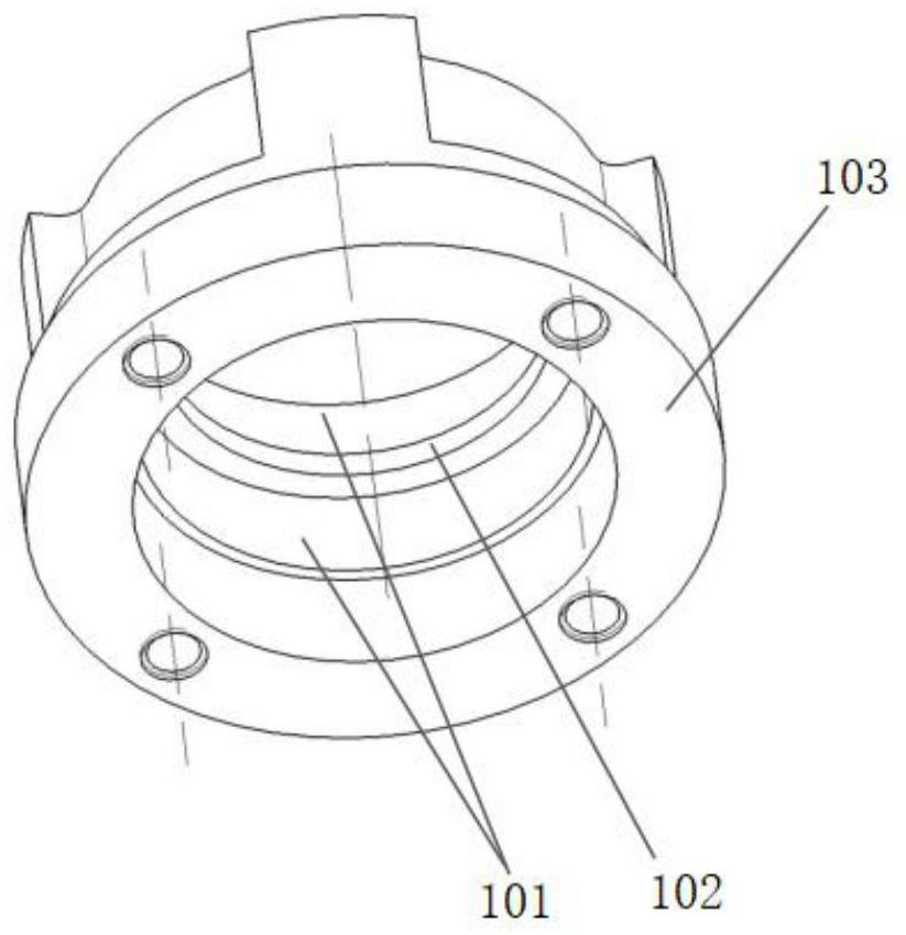
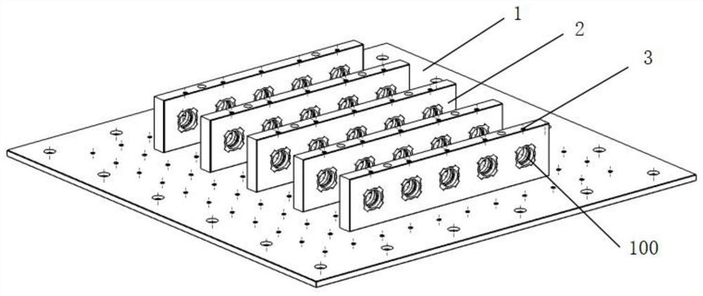
[0039] The measuring device is composed of a measuring plate 1, a fixing seat 2, and a fastening screw 3. image 3 A schematic diagram of the device is shown. The measuring plate is mainly used for the positioning and fixing of the fixing bases, and ensures that the distances between the fixing bases are equal. The fixing seat and fastening screws are mainly used for fixing the rotor bushings, and ensure that the distance between the rotor bushings in the fixing seat is equal. The fastening screws are mainly used for fixing the rotor bushings, and the rubber sleeve head 3.1 is fixed on the top to prevent Damage to the surface of the part.

[0040] Measuring plate:

[0041] The measuring plate is used for the positioning and...


PUM


Abstract

The invention relates to a measuring device and method for rapidly measuring a rotor shaft sleeve. The method comprises the steps of 1 preparing: 1.1, placing a measuring flat plate on a working platform of a three-coordinate measuring machine, enabling the measuring flat plate to be tightly attached to the working platform, enabling the X-axis direction and the Y-axis direction of the measuring flat plate to be consistent with the X-axis direction and the Y-axis direction of the working platform, and fixing the measuring flat plate on the working platform by a fastening screw; 1.2 fixing a plurality of groups of fixing seats on the measuring flat plate in parallel at equal intervals, and enabling the center connecting line of the two counterbores in the fixing seats to keep consistent with the X-axis direction or the Y-axis direction of the measuring flat plate; 1.3installing a plurality of workpieces in horizontal installation holes in the fixing seats one by one, ensuring that the positioning datum plane of the fixing seats makes full contact with the positioning datum plane of the rotor shaft sleeve, and then tightening fixing screws to fix workpieces; and 2 adopting a high-precision three-coordinate measuring machine with a star-shaped measuring head, and achieving rapid batch measurement of the workpieces by establishing a workpiece coordinate system and editing a cyclic measurement program. According to the invention, the measurement precision and the measurement efficiency of the workpieces are improved.

Description

technical field [0001] The invention belongs to the field of torque motor production and manufacturing, and relates to a measurement technology of a rotor shaft sleeve, in particular to a measuring device and a measurement method for rapidly measuring a rotor shaft sleeve. Background technique [0002] The torque motor has low manufacturing cost and reliable performance. It can provide stable torque to the load when the motor is running at a low speed. It is widely used in machinery manufacturing, aviation, navigation, weaponry and other fields. Torque motors are in great demand in scientific research and production, and the rotor bushing is an important part of the torque motor, and the efficient and accurate measurement of its various shapes and sizes is particularly important. [0003] Due to the structural characteristics of the rotor bushing 100, there is an annular beam 102 between the two precision bearing holes 101, which causes the existing precision measurement tec...

Claims


Application Information

Patent Timeline
Patent Type & Authority Applications(China)
IPC IPC(8): G01B21/04G01B21/14G01B21/24
CPCG01B21/04G01B21/047G01B21/14G01B21/24
Inventor 孔德杰徐海辉王保强于金洽杜卫国陈亚欧刘媛媛
Owner TIANJIN NAVIGATION INSTR RES INST
Why Eureka
Try Eureka