
OLT (Optical Line Terminal) equipment and optical path processing method

An optical line terminal and optical path technology, applied in the field of communication, can solve the problems of poor reliability and applicability of OLT equipment, large delay of user equipment, etc., and achieve the effect of improving reliability and applicability

Active Publication Date: 2021-12-31
HUAWEI TECH CO LTD
View PDF3 Cites 2 Cited by
  • Summary
  • Abstract
  • Description
  • Claims
  • Application Information

AI Technical Summary

Problems solved by technology

However, the replacement of the downlink interface needs to transfer all the user equipment on the failed downlink interface to the new downlink interface, which will still cause a large delay in the service of the user equipment due to the interface replacement
Therefore, the reliability and applicability of existing OLT equipment are poor

Method used


Image

  • OLT (Optical Line Terminal) equipment and optical path processing method
  • OLT (Optical Line Terminal) equipment and optical path processing method
  • OLT (Optical Line Terminal) equipment and optical path processing method

Examples


Embodiment 1

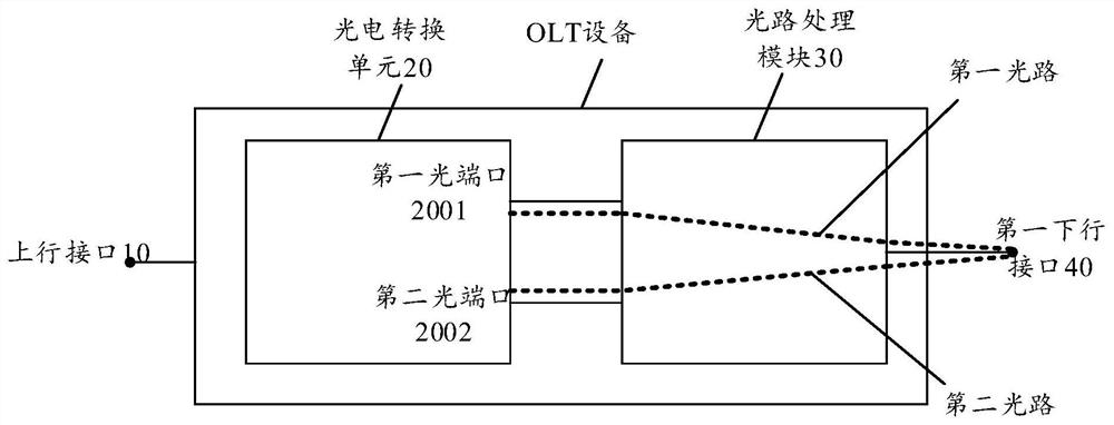
[0048] See image 3 , image 3 It is a schematic structural diagram of an OLT device provided in the embodiment of this application. Since the working principle of the OLT device in the uplink communication scenario and the downlink communication scenario is similar, but the processing sequence is the reverse process, so in the embodiment of the application, the structure and working principle of the OLT device provided in the application will be described in detail in the downlink communication scenario as an example. description of.

[0049] Such as image 3 As shown, the OLT device may include an uplink interface 10 , a photoelectric conversion unit 20 , an optical path processing module 30 and a first downlink interface 40 . Wherein, the function of the uplink interface 10 is the same as that of the uplink interface of the existing OLT device described above, and will not be repeated here. The function of the photoelectric conversion unit 20 is similar to that of the a...

Embodiment 2

[0076] See Figure 12 , Figure 12 It is a schematic flowchart of an optical path processing method provided in the embodiment of the present application. The optical path processing method is applicable to the OLT device described in Embodiment 1, and is specifically executed by the control device 50 included in the OLT device. The specific structure of the OLT device is as described in Embodiment 1, and will not be repeated in this embodiment. Such as Figure 11 As shown, the method includes the following steps:

[0077] S101, the control device 50 generates control information.

[0078] In some feasible implementation manners, when the control module 50 detects that the preset trigger condition is met, it can generate control information, and the control information is used to control the optical path processing module 30 to enable the connection between the first downlink interface and the first optical port. or enable the second optical path between the first downlin...


PUM


Abstract

The invention provides optical line terminal (OLT) equipment and an optical path processing method. The OLT equipment comprises a first downlink interface, a photoelectric conversion unit and an optical path processing module, wherein the photoelectric conversion unit comprises a first optical port and a second optical port. And the first downlink interface is respectively connected with the first optical port and the second optical port through the optical path processing module. And the optical path processing module is used for starting a first optical path between the first downlink interface and the first optical port or starting a second optical path between the first downlink interface and the second optical port. According to the OLT equipment provided by the invention, the optical path which can be enabled is established between the downlink interface and the at least two optical ports of the photoelectric conversion unit, so that the service influence on the user equipment caused by the fault of the downlink interface can be avoided, and the reliability and applicability of the OLT equipment are improved.

Description

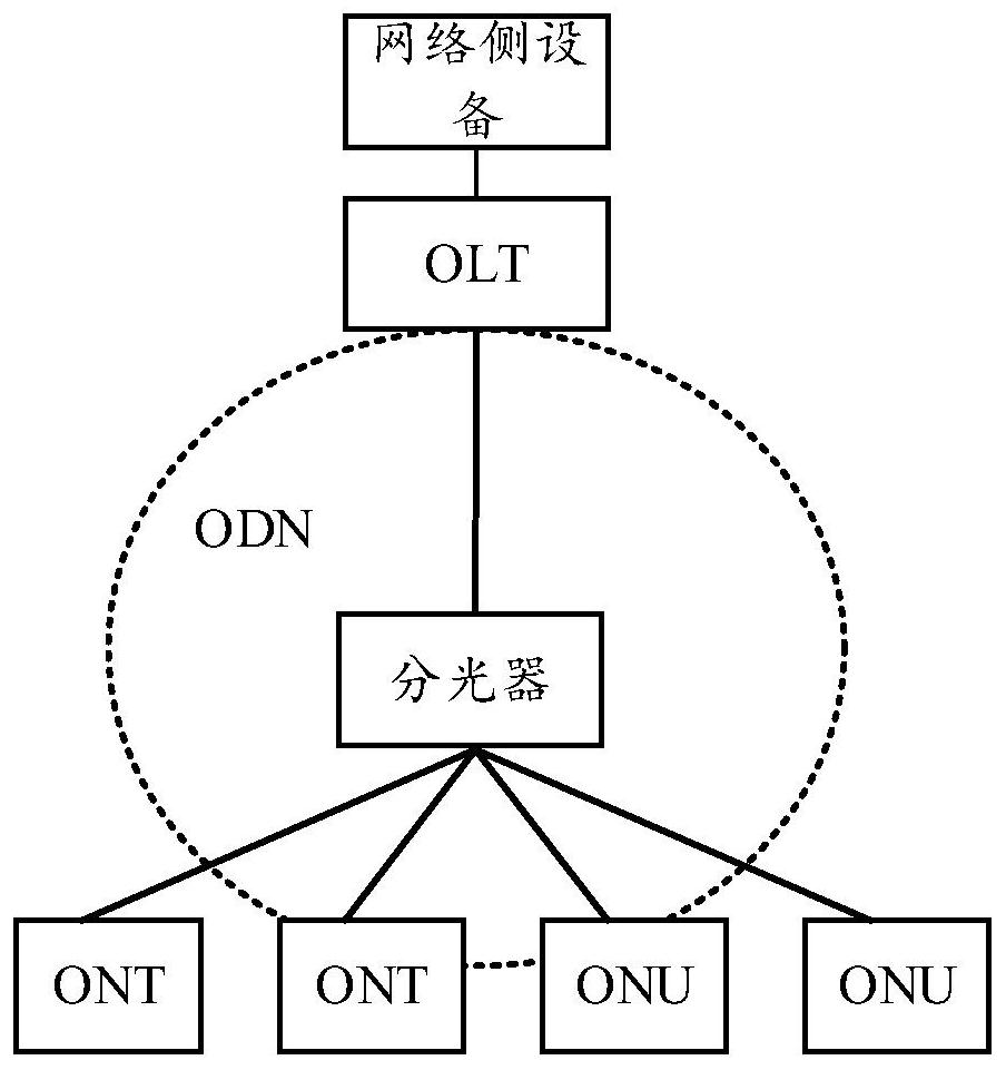
technical field [0001] The present application relates to the communication field, and in particular to an optical line terminal (optical line terminal, OLT) device and an optical line processing method. Background technique [0002] With the continuous development of communication technology, the application of optical communication technology is becoming more and more extensive. At the same time, in the optical communication network established based on the optical communication technology, the traditional network access system is gradually replaced by an optical access network (optical access network, OAN) system. Passive optical network (PON) is an implementation technology of optical access network, and PON is an optical access technology for point-to-multipoint transmission. See figure 1 , figure 1 It is a schematic diagram of a PON system architecture provided by the embodiment of this application. Such as figure 1 As shown, the optical line terminal (optical lin...

Claims


Application Information

Patent Timeline
Patent Type & Authority Applications(China)
IPC IPC(8): H04B10/079H04Q11/00
CPCH04Q11/0062H04Q11/0067H04B10/079H04Q2011/0081H04Q2213/1301H04Q2011/0083H04B10/038
Inventor 林连魁
Owner HUAWEI TECH CO LTD
Learn More