
Non-contact rotary scanning device for inner surface of bore

A rotary scanning, non-contact technology, applied in the direction of offensive equipment, weapon accessories, weapon testing, etc., can solve the problems of single parameter, unable to achieve positioning, and measurement devices are easily interfered by external factors, etc., to achieve simple control, simple structure, and improved The effect of efficiency and precision

Active Publication Date: 2021-12-31
NANJING UNIV OF SCI & TECH
View PDF6 Cites 0 Cited by
  • Summary
  • Abstract
  • Description
  • Claims
  • Application Information

AI Technical Summary

Problems solved by technology

However, the measurement device using photoelectric sensing technology generally needs to build a linear and rotary motion actuator outside the gun bore, which cannot realize the positioning inside the gun bore. Therefore, the accuracy of the device installation is extremely high, and the measuring device is easily interfered by external factors. The measurement devices of laser light triangulation detection technology and semiconductor laser collimation technology can only be limited to the measurement of local taper, circular runout, roundness, radius of gun bore and wrapping angle of the gun bore, and can only measure a single parameter each time

Method used


Image

  • Non-contact rotary scanning device for inner surface of bore
  • Non-contact rotary scanning device for inner surface of bore
  • Non-contact rotary scanning device for inner surface of bore

Examples


Embodiment Construction

[0024] In order to make the object, technical solution and advantages of the present invention clearer, the present invention will be further described in detail below in conjunction with the accompanying drawings and embodiments. It should be understood that the specific embodiments described here are only used to explain the present invention, not to limit the present invention. In addition, the technical features involved in the various embodiments of the present invention described below can be combined with each other as long as they do not constitute a conflict with each other.

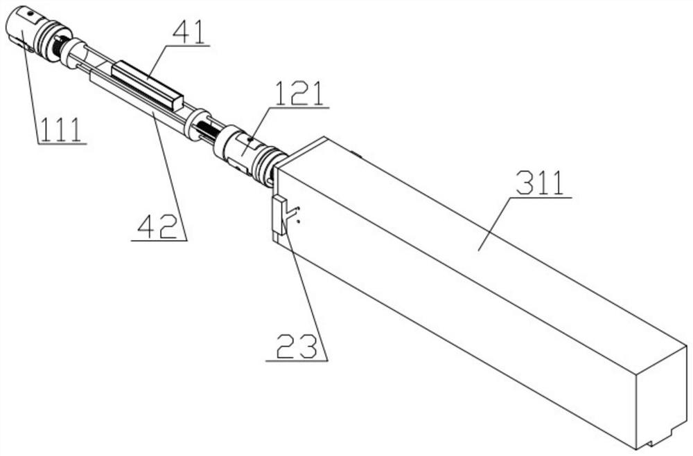
[0025] figure 1 It is a perspective view of a non-contact rotary scanning device for the inner surface of the gun bore constructed according to a preferred embodiment of the present invention, as figure 2 and image 3 As shown, the present embodiment is applicable to the measuring work of the rifling of the 30mm caliber gun.

[0026] When the present invention works, at first assemble extern...


PUM


Abstract

The invention provides a non-contact rotary scanning device for the inner surface of a bore. An image of a to-be-detected artillery rifling is obtained through coordination of a mechanical structure of a detection device and a magnetic image sensor, the non-contact rotary scanning device comprises a driving device, a transmission device, a first clamping device, a second clamping device, a measuring device and a monitoring device, the driving device is connected with the transmission device through a lead screw, the measuring device is connected with the transmission device through the lead screw, the first clamping device is connected with the transmission device through a first auxiliary rotating disc, the second clamping device is connected with an outer machine frame sealing cover of the driving device through a second circular column, the monitoring device is connected with the driving device through a stepping motor, and monitoring of the rotating speed and the rotating angle in the rotating process is achieved. According to the device, an arm is rotated in a rotating mode, a power source only needs one motor, the structure of the whole device is simplified, centering and positioning in the bore of the device are achieved through the clamping device, the device conforms to the use of a small-caliber bore, and the measurement precision and efficiency of relevant parameters of the bore are improved.

Description

technical field [0001] The invention relates to the field of measuring the rifling of a rifled gun, in particular to a non-contact rotary scanning device for the inner surface of a gun bore. Background technique [0002] As an important factor affecting the performance of artillery, rifling is an indicator that needs to be focused on during inspection. Most of the detection of small-caliber artillery bores adopts contact detection methods. Contact detection causes large detection errors due to wear and tear of detection tools and human factors. It cannot meet the detection requirements of fast and accurate gun bore. Therefore, driven by many factors such as the development of related technologies and the increasing demand for artillery applications, photoelectric sensing technology has gradually become the main way to complete detection. However, the measurement device using photoelectric sensing technology generally needs to build a linear and rotary motion actuator outsid...

Claims


Application Information

Patent Timeline
IPC IPC(8): F41A31/02
CPCF41A31/02
Inventor 秦晓泳宦昭润曲浩王一卓丁立波
Owner NANJING UNIV OF SCI & TECH
Learn More