
PC structure machining device

A processing device and mounting plate technology, which is applied in the direction of manufacturing tools, ceramic molding mandrels, ceramic molding machines, etc., can solve the problems such as difficult removal of mold sticks, and achieve the effect of easy unloading, smooth and simple pulling action, and avoiding collisions

Active Publication Date: 2021-12-31
阜阳市晶宫工业科技有限公司
View PDF20 Cites 2 Cited by
  • Summary
  • Abstract
  • Description
  • Claims
  • Application Information

AI Technical Summary

Problems solved by technology

[0003] Aiming at the deficiencies of the prior art, the purpose of the present disclosure is to provide a PC-built processing device, which solves the problem in the prior art that it is difficult to take out the mold stick after pouring

Method used


Image

  • PC structure machining device
  • PC structure machining device
  • PC structure machining device

Examples


Embodiment Construction

[0030] The following will clearly and completely describe the technical solutions in the embodiments of the present disclosure with reference to the accompanying drawings in the embodiments of the present disclosure. Apparently, the described embodiments are only some of the embodiments of the present disclosure, not all of them. Based on the embodiments in the present disclosure, all other embodiments obtained by persons of ordinary skill in the art without creative efforts fall within the protection scope of the present disclosure.

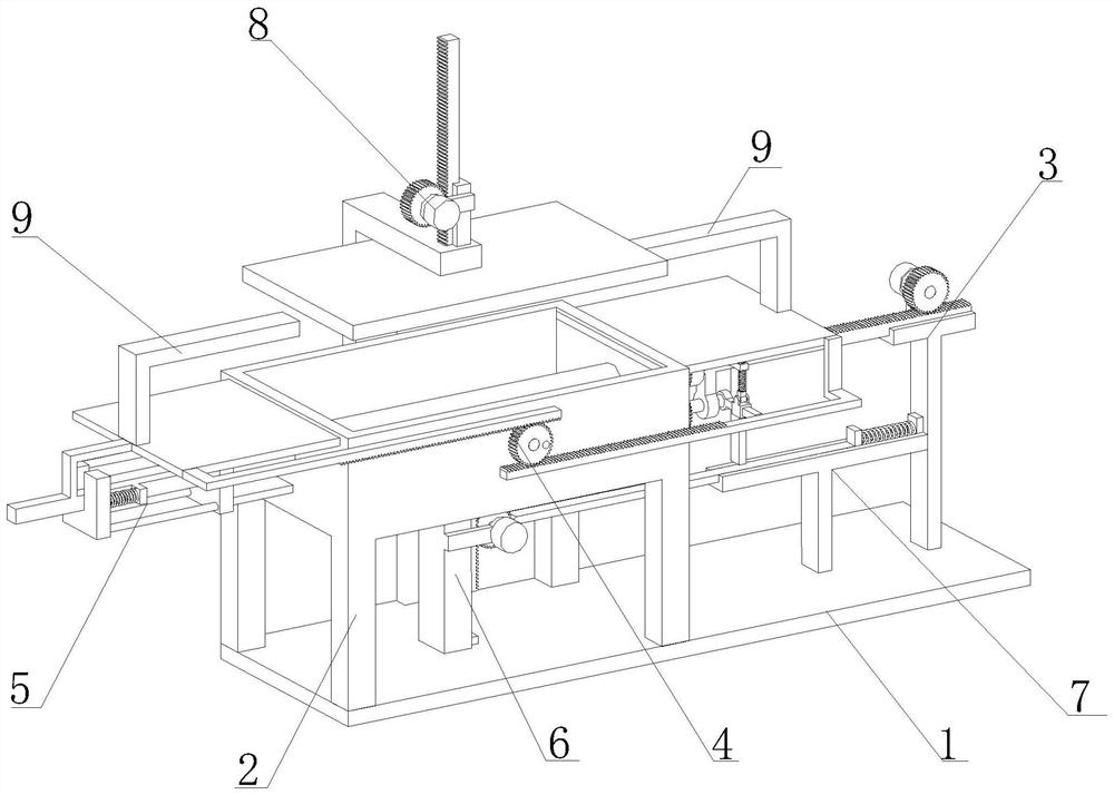
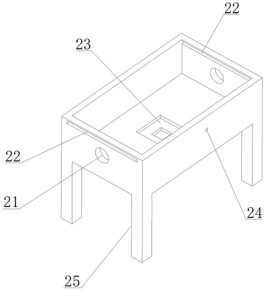
[0031] Such as Figure 1-2 As shown, a PC-built processing device includes a bottom plate 1 and a box body 2. The lower end of the box body 2 is provided with a plurality of support columns 25, and the support columns 25 and the bottom plate 1 are fixed to each other; the upper end of the box body 2 is open, and the concrete Pouring from the top of the box body 2 into the box body 2, and then realizing the pouring and molding of PC construction....


PUM


Abstract

The invention discloses a PC structure machining device, and belongs to the field of PC structure machining. The PC structure machining device comprises a box body, a mold bar inserting and drawing mechanism, an opening and closing mechanism, a limiting mechanism, a jacking mechanism, a locking mechanism and a downward pressing mechanism. The mold bar inserting and drawing mechanism is arranged on the box body, and a rotating assembly is arranged in the mold bar inserting and drawing mechanism, so that the drawing action of a mold bar is smoother and simpler, and axial strain of an inner circle of a cylindrical hole is avoided when the mold bar is drawn; by arranging the opening and closing mechanism and the limiting mechanism, control over the opening time of the upper end of the box body is achieved, and the situation that when concrete is poured into the box body, the mold bar cannot be inserted into the box body, and machining fails is avoided; by arranging the jacking mechanism and the locking mechanism, control over the jacking time of the jacking mechanism is achieved, and deformation of the mold bar is avoided; and the downward pressing mechanism is arranged, so that discharging of gas in the concrete is accelerated while the concrete is flattened.

Description

technical field [0001] The disclosure belongs to the field of PC construction and processing, and in particular relates to a processing device for PC construction. Background technique [0002] With the continuous development of science and technology, PC construction is more frequently used in the construction field. During production, PC construction is formed by pouring concrete into box molds; Insert the mold rod into the box mold, pull out the mold rod after pouring, and then take out the formed PC structure; but after the mold rod and concrete are poured together, the strength of the concrete makes it difficult to pull out the mold rod, and it is forced to pull out Can cause axial strain on the inner surface of the cylindrical bore on the PC build. Contents of the invention [0003] In view of the deficiencies in the prior art, the purpose of the present disclosure is to provide a PC-built processing device, which solves the problem in the prior art that it is diffi...

Claims


Application Information

Patent Timeline
Patent Type & Authority Applications(China)
IPC IPC(8): B28B7/18B28B7/28B28B17/00
CPCB28B7/18B28B7/285B28B17/00
Inventor 刘立超
Owner 阜阳市晶宫工业科技有限公司
Learn More