
Kitchen garbage recycling processor

A kitchen waste recycling technology, which is applied in the direction of presses, manufacturing tools, and solid waste removal, can solve problems such as unfavorable placement and use, kitchen waste feeding, and large extrusion chamber volume, and realizes small The effects of streamlined design, reduced design requirements, and reduced manufacturing costs

Inactive Publication Date: 2021-12-31
文明华
View PDF1 Cites 4 Cited by
  • Summary
  • Abstract
  • Description
  • Claims
  • Application Information

AI Technical Summary

Problems solved by technology

Although the kitchen waste disposer realizes the crushing and compression treatment of kitchen waste from the source, after the kitchen waste is crushed, it must be dehydrated and dried before being squeezed. The processing process is relatively complicated, and The pulverized kitchen waste is all compressed at one time, and the solid cake-shaped kitchen waste formed after compression has a large volume, which makes subsequent treatment difficult
At the same time, the volume of the extrusion chamber required is also relatively large, resulting in an excessively large volume of the entire processor, which is not conducive to placing and using in small areas such as families.
Moreover, the technical content disclosed by the kitchen waste disposer does not explain how to send the pulverized kitchen waste to the solid-liquid separation device, and how to squeeze the solid cake-shaped kitchen waste. What is the specific structure and how the squeezed garbage is put into the garbage storage room? There are no specific and detailed implementation methods and technical solutions. is ambiguous to people and therefore has problems implementing it

Method used


Image

  • Kitchen garbage recycling processor
  • Kitchen garbage recycling processor
  • Kitchen garbage recycling processor

Examples


Embodiment 1

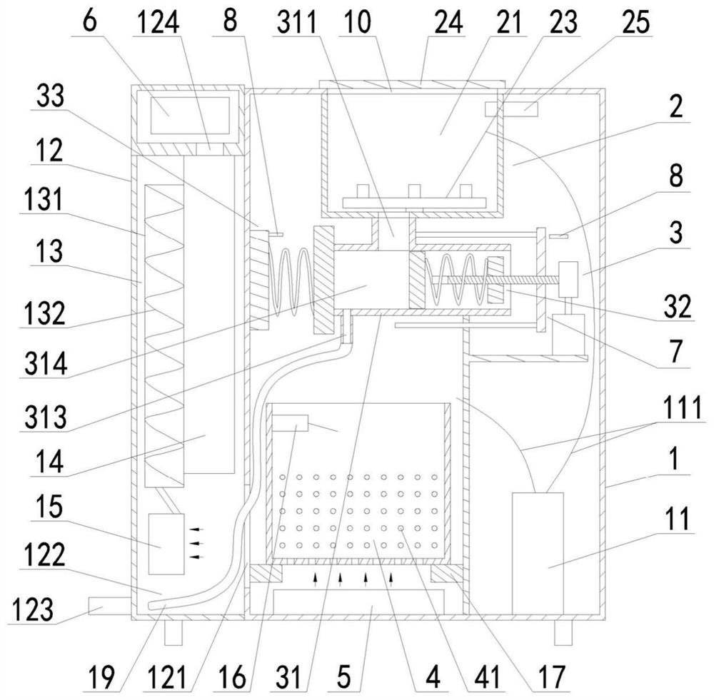
[0054] Such as figure 1 and Figure 10 As shown, the extrusion molding mechanism includes a forward pressure mechanism 32 and a reverse pressure mechanism 33, wherein the reverse pressure mechanism 33 seals the molded waste outlet 312 under normal conditions, and the quantitative extrusion cylinder 31 is positively pressed The mechanism 32 and the reverse pressing mechanism 33 form a quantitative forming cavity 314 for filling and compressing the crushed kitchen waste into small pieces. The reverse pressing mechanism 33 compresses the kitchen waste into small pieces. Finally, the top pressure is released to open the molded garbage outlet 312, so that the kitchen waste compressed into small pieces is pushed out of the quantitative molding cavity 314 by the forward pressure mechanism 32 and falls into the garbage collection bucket 4. The feeding port 311 is located at the quantitative molding The top of the chamber 314 is in communication with the pulverizing pool 21, and the d...

Embodiment 2

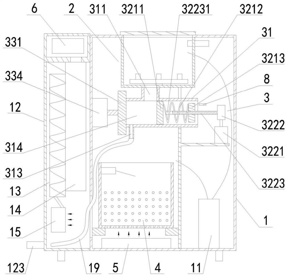
[0059] Such as figure 2 As shown, the extrusion molding mechanism includes a forward pressure mechanism 32 and a reverse pressure mechanism 33, wherein the reverse pressure mechanism 33 seals the molded waste outlet 312 under normal conditions, and the quantitative extrusion cylinder 31 is positively pressed The mechanism 32 and the reverse pressing mechanism 33 form a quantitative forming cavity 314 for filling and compressing the crushed kitchen waste into small pieces. The reverse pressing mechanism 33 compresses the kitchen waste into small pieces. Finally, the top pressure is released to open the molded garbage outlet 312, so that the kitchen waste compressed into small pieces is pushed out of the quantitative molding cavity 314 by the forward pressure mechanism 32 and falls into the garbage collection bucket 4. The feeding port 311 is located at the quantitative molding The top of the chamber 314 is in communication with the pulverizing pool 21, and the drainage hole 31...

Embodiment 3

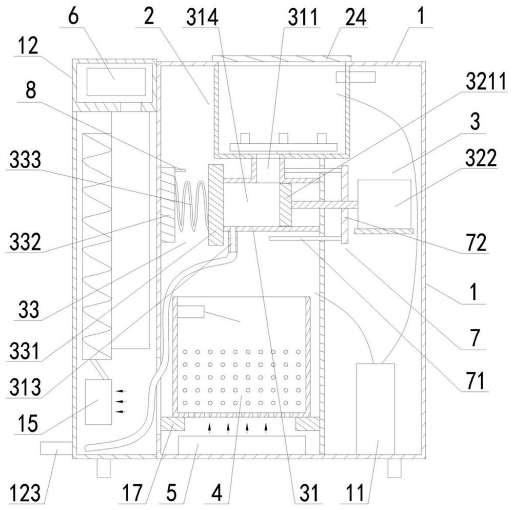
[0064] Such as image 3As shown, the extrusion molding mechanism includes a forward pressure mechanism 32 and a reverse pressure mechanism 33, wherein the reverse pressure mechanism 33 seals the molded waste outlet 312 under normal conditions, and the quantitative extrusion cylinder 31 is positively pressed The mechanism 32 and the reverse pressing mechanism 33 form a quantitative forming cavity 314 for filling and compressing the crushed kitchen waste into small pieces. The reverse pressing mechanism 33 compresses the kitchen waste into small pieces. Finally, the top pressure is released to open the molded garbage outlet 312, so that the kitchen waste compressed into small pieces is pushed out of the quantitative molding cavity 314 by the forward pressure mechanism 32 and falls into the garbage collection bucket 4. The feeding port 311 is located at the quantitative molding The top of the chamber 314 is in communication with the pulverizing pool 21, and the drainage hole 313 ...


PUM


Abstract

A kitchen waste recycling processor comprises a box body with a waste throwing opening in the upper portion, a waste smashing device arranged in the box body and communicating with the waste throwing opening, a waste collecting barrel arranged in the box body and located below the waste smashing device, and a drying device and a circuit control device which are arranged in the box body. And meanwhile, a quantitative extrusion forming device for separately compressing kitchen garbage crushed in the waste smashing device into small blocks is arranged in the box body and is positioned between the garbage smashing device and the waste collecting barrel. The quantitative extrusion forming device is used for performing certain-amount extrusion forming on the kitchen garbage crushed in the waste smashing device each time, so that the kitchen garbage crushed in the waste smashing device can be separately compressed into small solid blocks, and the small solid blocks are turned into pet feed, or organic fertilizer and biofuel for use; and in addition, the extrusion forming size of the kitchen garbage is effectively reduced, and subsequent recycling and reutilization treatment of the kitchen garbage are facilitated.

Description

technical field [0001] The invention relates to a kitchen waste treatment device, in particular to a kitchen waste recovery and reuse processor. Background technique [0002] In people's daily life, a large amount of kitchen waste will be produced. Kitchen waste has become one of the main sources of pollution in the city, which is very harmful to human health and the environment. At present, incineration and landfill are the two main ways to dispose of kitchen waste. However, incineration is likely to produce harmful gases such as dioxins, and landfill is likely to cause soil and groundwater pollution. [0003] In fact, kitchen waste can be made into fertilizer or feed through different processes. It is a waste of resources to use incineration or landfill, but no one can give an answer before how to turn waste into treasure. Because the kitchen waste is made into fertilizer or feed, the collection and treatment costs must be considered. First, the collection cost is greate...

Claims


Application Information

Patent Timeline
Patent Type & Authority Applications(China)
IPC IPC(8): B09B3/00B09B5/00B30B9/06B30B9/30
CPCB09B3/00B09B5/00B30B9/062B30B9/306B30B9/301B30B9/3014B30B9/3007
Inventor 文明华
Owner 文明华
Learn More