Dry powder dialysis bottle

A dialysis bottle and dry powder technology, applied in the field of medical devices, can solve the problems of inability to precisely control the filtration precision, unable to meet the filtration precision, and the use requirements of hemodialysis, and achieve the effects of good sealing, improved yield, and reduced processing costs.

Pending Publication Date: 2021-12-31
成都德瑞鑫包装制品有限公司
View PDF0 Cites 0 Cited by
  • Summary
  • Abstract
  • Description
  • Claims
  • Application Information

AI Technical Summary

Problems solved by technology

The dry powder dialysis bottle is used to package and store the hemodialysis dry powder. The hemodialysis dry powder is directly put into the bottle after the production is completed. Many dry powders with insufficient particle uniformity and large particles will also be stored in the bottle and cannot be removed, affecting the overall product. the quality of
[0003] In addition, the dry powder dialysis bottle in the prior art needs to be assembled due to the filter mechanism in the middle of the bottle body, so the inlet part needs to be made separately from the bottle body, and then connected by heat welding. Heat welding usually uses the inlet of Industry 4.0 It takes at least 47 seconds for the equipment to process from two separately produced parts entering the machine and then welding to the product exiting the machine, and the highest yield rate can only reach 96%.
Therefore, the dry powder dialysis bottle in the prior art has the problems of high cost, low efficiency and low yield in the production process.
[0004] In the prior art, the filter mechanism in the middle of the dry powder dialysis bottle usually uses a sintered PE plastic filter. This sintered filter controls the filtration accuracy through the sintered plastic particle size, resulting in the inability to accurately control the filtration accuracy. Often As a result, the filtration accuracy cannot meet the requirements of hemodialysis

Method used


Image

  • Dry powder dialysis bottle
  • Dry powder dialysis bottle
  • Dry powder dialysis bottle

Examples


Embodiment Construction

[0020] The specific embodiments of the present invention are described below so that those skilled in the art can understand the present invention, but it should be clear that the present invention is not limited to the scope of the specific embodiments. For those of ordinary skill in the art, as long as various changes Within the spirit and scope of the present invention defined and determined by the appended claims, these changes are obvious, and all inventions and creations using the concept of the present invention are included in the protection list.

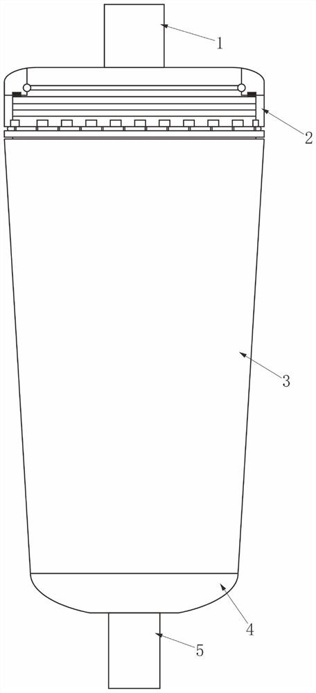
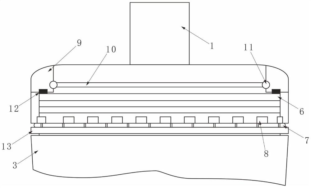
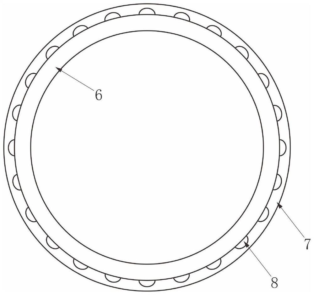
[0021] Such as Figure 1 to Figure 3 As shown, the dry powder dialysis bottle of this program includes an Erlenmeyer flask body 3 with a large upper part and a smaller lower part. The upper end of the Erlenmeyer flask body 3 is provided with a connecting part 6, and the connecting part 6 is provided with an upper cover 2, and the upper cover 2 is connected to the part 6 is detachably connected; the upper end of the upper co...


PUM


Abstract

The invention discloses a dry powder dialysis bottle. The dry powder dialysis bottle comprises a big-end-up conical bottle body, wherein a connecting part is arranged at the upper end of the conical bottle body, an upper cover is arranged on the connecting part, and the upper cover is detachably connected with the connecting part; a discharge inlet is formed in the upper end of the upper cover; a discharge outlet is formed in the lower end of the conical bottle body; a limiting convex ring is arranged at the upper end of the inner wall of the upper cover, the upper end of the connecting part is in contact with the limiting convex ring, and silica gel rings cooperating with the connecting part are arranged on the lower surface of the limiting convex ring; and a filtering membrane is arranged in the limiting convex rings, the filtering membrane is arranged on elastic mounting rings, and the mounting rings are placed in an annular groove formed in the inner walls of the limiting convex rings. According to the scheme, the filtering membrane is arranged on the upper cover, impurities in dialysate can be effectively filtered out, and besides, the upper cover is detachably connected with the conical bottle body. The upper cover extrudes the silica gel rings, so that good sealing performance is ensured, and the situation of powder leakage is avoided.

Description

technical field [0001] The invention relates to the technical field of medical devices, in particular to a dry powder dialysis bottle. Background technique [0002] Hemodialysis dry powder is suitable for sodium bicarbonate dialysis treatment of patients with acute and chronic renal failure or acute dialyzable poison poisoning. It is a special raw material for preparing hemodialysis solution, which is used to treat renal failure, anuria and electrolyte disturbance caused by drug poisoning. The dry powder dialysis bottle is used to package and store the hemodialysis dry powder. The hemodialysis dry powder is directly put into the bottle after the production is completed. Many dry powders with insufficient particle uniformity and large particles will also be stored in the bottle and cannot be removed, affecting the overall product. the quality of. [0003] In addition, the dry powder dialysis bottle in the prior art needs to be assembled due to the filter mechanism in the mi...

Claims


Application Information

Patent Timeline
Patent Type & Authority Applications(China)
IPC IPC(8): A61J1/05A61J1/14A61M1/16
CPCA61M1/1621A61M1/1654A61M1/1668A61J1/05A61J1/1443A61J1/1418A61J1/1406
Inventor 曾燕
Owner 成都德瑞鑫包装制品有限公司
Why Eureka
Try Eureka