Mechanical arm and surgical navigation positioning system

A robotic arm and limit slot technology, used in surgical navigation systems, surgical manipulators, surgery, etc., can solve the problems of large number of trolleys, unfavorable information interaction, large impact of brake electromagnets, short life of electromagnetic brakes, etc., to reduce motion. The effect of planning difficulty, improving accuracy, and facilitating surgical operations

Pending Publication Date: 2021-12-31
NANJING TUODAO MEDICAL TECHNOLOGY CO LTD
View PDF0 Cites 0 Cited by
  • Summary
  • Abstract
  • Description
  • Claims
  • Application Information

AI Technical Summary

Problems solved by technology

[0004] 1. Sometimes it is necessary for a doctor to operate the robot to control the mechanical arm during manipulation. In the prior art, an electromagnetic brake is used to brake the mechanical arm, but the electromagnet of the brake has a large impact, which is easy to cause vibration, resulting in easy vibration after the mechanical arm is powered off. , especially the brakes on the base joints will cause the robot to shake a lot, and at the same time start and brake frequently. The collision of the electromagnet will shorten the life of the electromagnetic brake and require frequent maintenance and replacement;
[0005] 2. During use, it is necessary to use trolleys including C-arm machines, robotic arms, optical positioning systems, etc. The large number of trolleys results in a large footprint, and the area of ​​hospital operating rooms is small, requiring frequent and heavy movements during the operation The unique C-arm machine and mechanical arm are inconvenient for doctors to operate;
[0006] 3. The large number of trolleys makes the operation process complicated, and there are many auxiliary actions during the operation, so the operation efficiency needs to be further improved;
[0007] 4. The large number of trolleys is not conducive to information interaction, the system stability is not high, the maintenance cost is high, and when a device has a problem, the operation cannot be performed

Method used


Image

  • Mechanical arm and surgical navigation positioning system
  • Mechanical arm and surgical navigation positioning system
  • Mechanical arm and surgical navigation positioning system

Examples


Embodiment Construction

[0059] The present invention will be further explained below in conjunction with the accompanying drawings and specific embodiments.

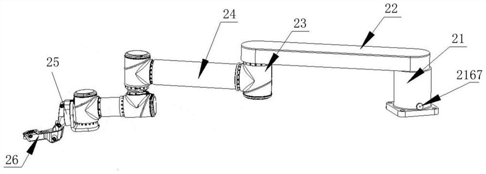
[0060] figure 1 It is a structural schematic diagram of the mechanical arm of the present invention, as figure 1 As shown, the mechanical arm of the present invention includes a base joint 21, a passive arm 22, and several connecting rods 24 connected sequentially through the joint 23, wherein the base joint 21 is fixedly installed, and the driven arm 22 is rotatably installed on the base joint 21. The first Two connecting rods 24 are connected with the ends of the passive arm 22 through joints 23. The end of the last connecting rod is the end of the mechanical arm 25. An end bracket 26 is fixedly installed on the end of the mechanical arm 25, and an execution sleeve is installed on the end bracket 26. . A manual brake is provided in the base joint 21. The mechanical arm of the present invention is composed of the degree of freedom of the pas...


PUM


Abstract

The invention discloses a mechanical arm and a surgical navigation and positioning system. The mechanical arm comprises: a base joint; a driven arm which is rotationally mounted on the base joint; and connecting rods which are sequentially connected in a matched mode through joints, wherein the first connecting rod is connected with the driven arm in a matched mode through joints. The base joint comprises a hollow base and a rotating shaft rotationally mounted in the base, and the driven arm is fixedly connected with the rotating shaft; and a braking assembly matched with the end face of the rotating shaft to achieve braking is installed in the base and located below the rotating shaft. According to the mechanical arm, self-locking of the mechanical arm can be achieved, and the problems that an existing brake is large in power-off self-locking vibration and short in service life and needs to be frequently replaced are solved. According to the invention, the occupied space of the trolley in the operation can be reduced, a doctor can conveniently carry out the operation in the operation, the information interaction of each device can be reduced, the operation efficiency of the doctor is improved, and the operation time is shortened.

Description

technical field [0001] The invention relates to the field of robot structures, in particular to a mechanical arm joint and a surgical navigation and positioning system. Background technique [0002] With the rapid development of medical technology and robot technology, in recent years, orthopedic surgery robot navigation system has been widely used in major hospitals at home and abroad, because it has high positioning accuracy, less intraoperative bleeding, and postoperative recovery compared with traditional orthopedic surgery. The advantage of being fast has received a lot of praise from doctors and patients. At present, the conventional orthopedic surgical robot system is composed of a C-arm machine, a display screen, a robotic arm, an operating table, and an optical positioning system. For positioning and navigation, the display screen is usually integrated on the C-arm machine for surgical operation, the optical positioning system is used to assist the robotic arm to r...

Claims


Application Information

Patent Timeline
IPC IPC(8): A61B34/30A61B34/20A61B34/10
CPCA61B34/30A61B34/20A61B34/10A61B34/70A61B2034/107A61B2034/108A61B2034/2065
Inventor 程敏
Owner NANJING TUODAO MEDICAL TECHNOLOGY CO LTD
Why Eureka
Try Eureka