Method for calculating steady-state control quantity of new energy grid-connected system

A steady-state control and calculation method technology, applied in the direction of AC network circuit, design optimization/simulation, single-network parallel feeding arrangement, etc., can solve the problems of output setting limit, non-convergence, limited actual effect, etc., to achieve reduction The effect of small steady-state time

Pending Publication Date: 2021-12-28
POWER GRID PLANNING RES INST OF GUIZHOU POWER GRID CO LTD +1
View PDF0 Cites 0 Cited by
  • Summary
  • Abstract
  • Description
  • Claims
  • Application Information

AI Technical Summary

Problems solved by technology

[0003] In order to improve the simulation efficiency of grid-connected new energy power generation systems and reduce the time it takes for the system to reach a steady state from zero state, some technical solutions have been applied, but there are still defects: set an empirical value for the control parameters as the initial default value, Or set a limit for the output of the PI controller. These methods have limited practical effects and require a lot of time for parameter debugging. If unreasonable parameters are input, the system may become unstable and the results will not converge.
[0004] Connect the equivalent ideal voltage source before the new energy power generation system is connected to the grid, and then switch the line to connect the new energy power generation system to the grid after the system is stable. Although this method can charge the capacitor or inductance in the system before the grid connection Discharge, to a certain extent, reduces the time for the system to reach a steady state after grid connection, but it still cannot avoid the transient process during line switching, causing unnecessary fluctuations in the system and the risk of instability
[0005] Through the power flow calculation, first obtain the grid-connected point voltage and offset phase angle in the steady state of the system, and then calculate the initial value of the PI controller in the control system, so that the system can start from the steady state value of the PI controller to reduce the time for the system to reach the steady state Time, this method only considers the steady-state start-up of the controller of the power electronic converter in the system, but does not consider the steady-state parameters of the new energy power generation module. For the control of the new energy power generation module, such as maximum power point tracking, boost conversion, etc. , it still starts from zero state, and does not consider the start-up process and time for the charging and discharging elements in the system to reach a steady state

Method used


Image

  • Method for calculating steady-state control quantity of new energy grid-connected system
  • Method for calculating steady-state control quantity of new energy grid-connected system
  • Method for calculating steady-state control quantity of new energy grid-connected system

Examples


Embodiment 1

[0055] Refer Figure 1 ~ 8 , A first embodiment of the present invention, this embodiment provides a new steady-state control amount calculating energy grid system, comprising:

[0056] S1: the new energy grid computing system as PQ node and its trend;

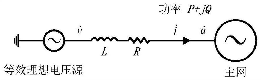
[0057] Refer figure 1 , New energy grid system as a whole, and is equivalent to an ideal voltage source access large grid; The active power P and reactive power injected into the grid of the set Q, is obtained by calculating the new flow energy grid system and network voltage

[0058] Wherein Incidentally, setting of the injection grid active power P and reactive power Q is a reference value set in the artificial electromagnetic transient simulation, active 1pu e.g., reactive power 0, as a reference control the overall power system, can take any value (0 ~ 1pu) system according to the study.

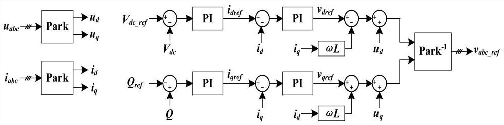
[0059] S2: According to the results, and using the calculated flow module 100 calculates the steady-state control amount;

[0060] Steady-s...


PUM


Abstract

The invention discloses a method for calculating steady-state control quantity of a new energy grid-connected system, and the method is characterized in that the method comprises the steps: taking the new energy grid-connected system as a PQ node, and carrying out the load flow calculation of the new energy grid-connected system; calculating a steady-state control quantity by utilizing a calculation module according to a load flow calculation result; and starting grid connection by taking the steady-state control quantity as an initial value of simulation output. The method is suitable for all new energy grid-connected systems based on the voltage source converter, the time for the system to reach the steady state is greatly shortened, and the simulation efficiency is improved on the premise that the system stability and the simulation precision are guaranteed.

Description

Technical field [0001] Technical Field The present invention relates to an electromagnetic transient simulation, in particular, it relates to a new steady-state control amount of the energy grid system calculation. Background technique [0002] With the rapid economic and social development, the demand for electricity is also growing, development and use of clean energy-based development of new energy sources has become a trend in today's power industry. The large-scale development of new energy grid energy structure has changed, the impact of new energy power generation for grid stability and security are more and more attention, become a hot research. The system model building new energy generation and new energy grid by means of electromagnetic transient simulation tools Simulation start-up and control of new energy power generation system, it is an efficient and economical means of research. A typical embodiment of the new energy system model by the new grid-energy power gene...

Claims


Application Information

Patent Timeline
Patent Type & Authority Applications(China)
IPC IPC(8): H02J3/38G06F30/20
CPCH02J3/381G06F30/20H02J2203/10H02J2203/20H02J2300/24H02J2300/28Y02E10/56
Inventor 李庆生袁智勇唐学用雷金勇马覃峰潘姝慧万会江周长城孙斌白浩张裕李旭李震孙方坤
Owner POWER GRID PLANNING RES INST OF GUIZHOU POWER GRID CO LTD
Why Eureka
Try Eureka