Mechanical stamping die facilitating discharging

A technology of mechanical stamping and mould, which is applied in the direction of manufacturing tools, metal processing equipment, stripping devices, etc., and can solve the problem of inconvenient waste discharge from moulds, etc.

Inactive Publication Date: 2021-12-28
SHENZHEN YI GU DE TECH CO LTD
View PDF0 Cites 0 Cited by
  • Summary
  • Abstract
  • Description
  • Claims
  • Application Information

AI Technical Summary

Problems solved by technology

[0003] Existing mechanical stamping dies generally focus on removing large pieces of waste, while ignoring small waste such as debris. The debris in the long-term use of the mold is accumulated and squeezed into high-density blocks Retained in the mold, it is not convenient for various waste materials generated by the mold to be discharged from the mold in time

Method used


Image

  • Mechanical stamping die facilitating discharging
  • Mechanical stamping die facilitating discharging
  • Mechanical stamping die facilitating discharging

Examples


Embodiment Construction

[0024] The technical solution of this patent will be further described in detail below in conjunction with specific embodiments.

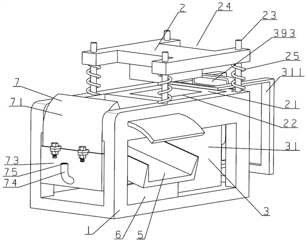
[0025] In one example, see Figure 1~Figure 5 , a mechanical stamping die for convenient discharge, including a support frame 1, and also includes:

[0026] Mold structure 2, the mold structure 2 includes a fixed mold 21 fixedly connected with the support frame 1, the middle part of the fixed mold 21 is provided with a punching hole 22, and one side of the support frame 1 is fixedly installed with multiple groups of guide rods 23, so The guide rod 23 is slidingly connected with a movable mold 24, and the movable mold 24 is connected with the support frame 1 by a first spring 25;

[0027] Discharging device 3, described discharging device 3 comprises the main frame 31 that is fixedly installed on support frame 1 side, and described main frame 31 is connected with carrier frame 33 by second spring 32, and described carrier frame 33 is connected with...


PUM


Abstract

The invention relates to the technical field of stamping dies, in particular to a mechanical stamping die facilitating discharging. The mechanical stamping die comprises a supporting frame and further comprises a die structure and a discharging device. The die structure comprises a fixed die fixedly connected with the supporting frame. A blanking hole is formed in the middle of the fixed die. Multiple guide rods are fixedly mounted on one side of the supporting frame and slidably connected with a movable die. The discharging device comprises a main case fixedly mounted on one side of the supporting frame. The main case is connected with a plate carrying frame through a second spring. A movable pulley block is fixedly mounted on one side face of the plate carrying frame and connected with a fixed pulley block fixedly mounted in the main case through a pull wire. One end of the pull wire is fixedly connected with a reel. The reel is connected with an air blowing structure fixedly connected with the main case through a transmission shaft. The plate carrying frame is connected with a pushing frame through a transmission structure. According to the mechanical stamping die, various waste materials generated in the blanking process can be conveniently separated from the fixed die in time.

Description

technical field [0001] The invention relates to the technical field of stamping dies, in particular to a mechanical stamping die for convenient material discharge. Background technique [0002] Stamping is a pressure processing method that uses a mold driven by a press to apply pressure to the material to cause separation or plastic deformation, so as to achieve the effect of plasticity or cutting, and then obtain the required parts. [0003] Existing mechanical stamping dies generally focus on removing large pieces of waste, while ignoring small waste such as debris. The debris in the long-term use of the mold is accumulated and squeezed into high-density blocks Retained in the mold, it is not convenient for various waste materials generated by the mold to be discharged from the mold in time. [0004] For this reason, those skilled in the art have proposed a mechanical stamping die for convenient discharge to solve the problems raised in the background above. Contents of...

Claims


Application Information

Patent Timeline
IPC IPC(8): B21D28/14B21D28/04B21D28/00B21D45/00B21D55/00
CPCB21D28/14B21D28/04B21D28/00B21D45/00B21D55/00
Inventor 张美灵肖芳
Owner SHENZHEN YI GU DE TECH CO LTD
Why Eureka
Try Eureka