
One-way heat conduction device

A one-way, thermal expansion layer technology, applied in the direction of modification by conduction heat transfer, cooling/ventilation/heating transformation, electrical components, etc., which can solve problems such as safety hazards, overheating of electronic components, and inability of heat conduction devices to dissipate heat. , to avoid excessive heat dissipation, good thermal conductivity, simple and efficient preparation method

Pending Publication Date: 2021-12-24
太仓市华盈电子材料有限公司
View PDF0 Cites 0 Cited by
  • Summary
  • Abstract
  • Description
  • Claims
  • Application Information

AI Technical Summary

Problems solved by technology

[0003] The current heat conduction device is generally only suitable for the environment where the temperature of the electronic components is higher than the external temperature. If the external environment temperature of the equipment is too high and the electronic components are too high, the heat conduction device will not be able to achieve a good heat dissipation effect, and even the electronic components will appear. Already in a heating state, the heat conduction device still conducts the heat of the external environment to the electronic components, which leads to overheating of the electronic components, resulting in potential safety hazards

Method used


Image

  • One-way heat conduction device
  • One-way heat conduction device
  • One-way heat conduction device

Examples


Embodiment Construction

[0035] The present invention will be described in detail below in conjunction with various embodiments shown in the drawings. However, these embodiments do not limit the present invention, and structural, method, or functional changes made by those skilled in the art according to these embodiments are included in the protection scope of the present invention.

[0036] It should be noted that when an element is referred to as being “fixed” to another element, it can be directly on the other element or there can also be an intervening element. When an element is referred to as being "connected to" another element, it can be directly connected to the other element or intervening elements may also be present. In the illustrated embodiments, directional representations, ie, up, down, left, right, front and rear, etc., are relative to explain that the structure and movement of the various components in the present application are relative. These representations are pertinent when t...


PUM

PropertyMeasurementUnit
Melting pointaaaaaaaaaa

Abstract

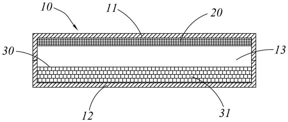
The invention discloses a one-way heat conduction device which comprises the components of a main body which is provided with a closed vacuum cavity which is provided with a first surface and a second surface which are oppositely arranged; a capillary structure is arranged on the first surface, and the capillary structure is filled with a phase change working medium; an organic vesicle layer is arranged on the second surface and can expand with heat and contract with cold along with the change of temperature, and the organic vesicle layer is provided with a plurality of organic vesicles. the one-way heat conduction can be realized; the heating element can be prevented from being damaged due to overheating caused by reverse heat conduction in the heat dissipation process, and excessive heat dissipation of the heating element in the heat dissipation process can be avoided; by reasonably selecting the phase change working medium filled in the capillary structure, the vaporization temperature of the phase change working medium can be controlled, so that the heat conduction device can be suitable for working scenes with various heat conduction requirements, and the heat conduction process can be accurately controlled.

Description

technical field [0001] The invention belongs to the technical field of heat conduction devices, and in particular relates to a one-way heat conduction device. Background technique [0002] With the rapid progress of electronic technology, electronic components are becoming more and more miniaturized, but their power consumption is increasing, so that heat dissipation technology seriously restricts the development of electronic technology. Therefore, it is particularly important to solve the heat dissipation problem of electronic components. [0003] The current heat conduction device is generally only suitable for the environment where the temperature of the electronic components is higher than the external temperature. If the external environment temperature of the equipment is too high and the electronic components are too high, the heat conduction device will not be able to achieve a good heat dissipation effect, and even the electronic components will appear. Already in...

Claims


Application Information

Patent Timeline
IPC IPC(8): H05K7/20
CPCH05K7/20336H05K7/20381H05K7/2039
Inventor 任晓英林连凯钟海军
Owner 太仓市华盈电子材料有限公司
Learn More