
Rotating shaft structure, centrifugal air compressor and vehicle

An air compressor and shaft structure technology, applied in the field of compressors, can solve the problems of increased bearing capacity of the top foil, large deformation of the corrugated foil, collision, etc., and achieve the effect of eliminating collision and preventing air film instability

Pending Publication Date: 2021-12-24
GREE ELECTRIC APPLIANCES INC
View PDF0 Cites 2 Cited by
  • Summary
  • Abstract
  • Description
  • Claims
  • Application Information

AI Technical Summary

Problems solved by technology

[0007] However, since the corrugated foil is an elastic structure, when the air compressor is subjected to abnormal shocks (such as breakdown, surge, sudden acceleration and deceleration of the car, etc.), the foil dynamic pressure gas radial bearing at one end of the rotor will receive additional shock loads, The deformation of the corrugated foil is too large, the bearing capacity of the top foil increases suddenly, and the air film is easily damaged, resulting in direct friction between the motor shaft and the foil dynamic pressure gas radial bearing, or the friction between the rotor of the air compressor and the stationary part.
Moreover, when the air compressor rotates at high speed, when the single load of the foil dynamic pressure gas radial bearing at both ends of the rotor is not equal to the single load of the radial bearing foil, it is easy to make the rotor tilt to one side, causing the foil dynamic pressure gas radial The air film formed between the bearing and the rotor is unstable, and the rotor and the foil dynamic pressure gas radial bearing collide with each other

Method used


Image

  • Rotating shaft structure, centrifugal air compressor and vehicle
  • Rotating shaft structure, centrifugal air compressor and vehicle
  • Rotating shaft structure, centrifugal air compressor and vehicle

Examples


Embodiment Construction

[0035] In order to make the above objects, features and advantages of the present invention more comprehensible, specific implementations of the present invention will be described in detail below in conjunction with the accompanying drawings. In the following description, numerous specific details are set forth in order to provide a thorough understanding of the present invention. However, the present invention can be implemented in many other ways different from those described here, and those skilled in the art can make similar improvements without departing from the connotation of the present invention, so the present invention is not limited by the specific embodiments disclosed below.

[0036] In describing the present invention, it should be understood that the terms "center", "longitudinal", "transverse", "length", "width", "thickness", "upper", "lower", "front", " Back", "Left", "Right", "Vertical", "Horizontal", "Top", "Bottom", "Inner", "Outer", "Clockwise", "Counte...


PUM


Abstract

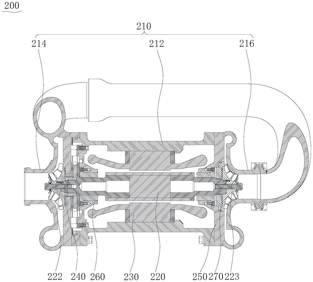
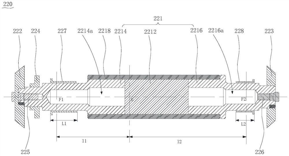
The invention relates to a rotating shaft structure, a centrifugal air compressor and a vehicle. The rotating shaft structure comprises a rotor, an impeller assembly, a thrust disc, a first-stage radial bearing and a second-stage radial bearing, wherein the rotor comprises a first shaft section and a second shaft section which are sequentially arranged in the axial direction; the impeller assembly comprises at least one impeller, and the first shaft section and / or the second shaft section are / is sleeved with the impellers; the thrust disc is arranged on the first shaft section of the rotor in a sleeving manner; and the first-stage radial bearing is arranged on the first shaft section of the rotor in a sleeving manner, the second-stage radial bearing is arranged on the second shaft section of the rotor in a sleeving manner, and the length of the first-stage radial bearing is greater than that of the second-stage radial bearing, so that the force per unit area of the first-stage radial bearing is equal to that of the second-stage radial bearing. According to the rotating shaft structure, the length of the first-stage radial bearing is increased, so that the force per unit area of a radial support wave foil of the first-stage radial bearing is reduced, the rotor can be prevented from inclining towards the side where the first shaft section is located, and stable operation of the centrifugal air compressor is ensured.

Description

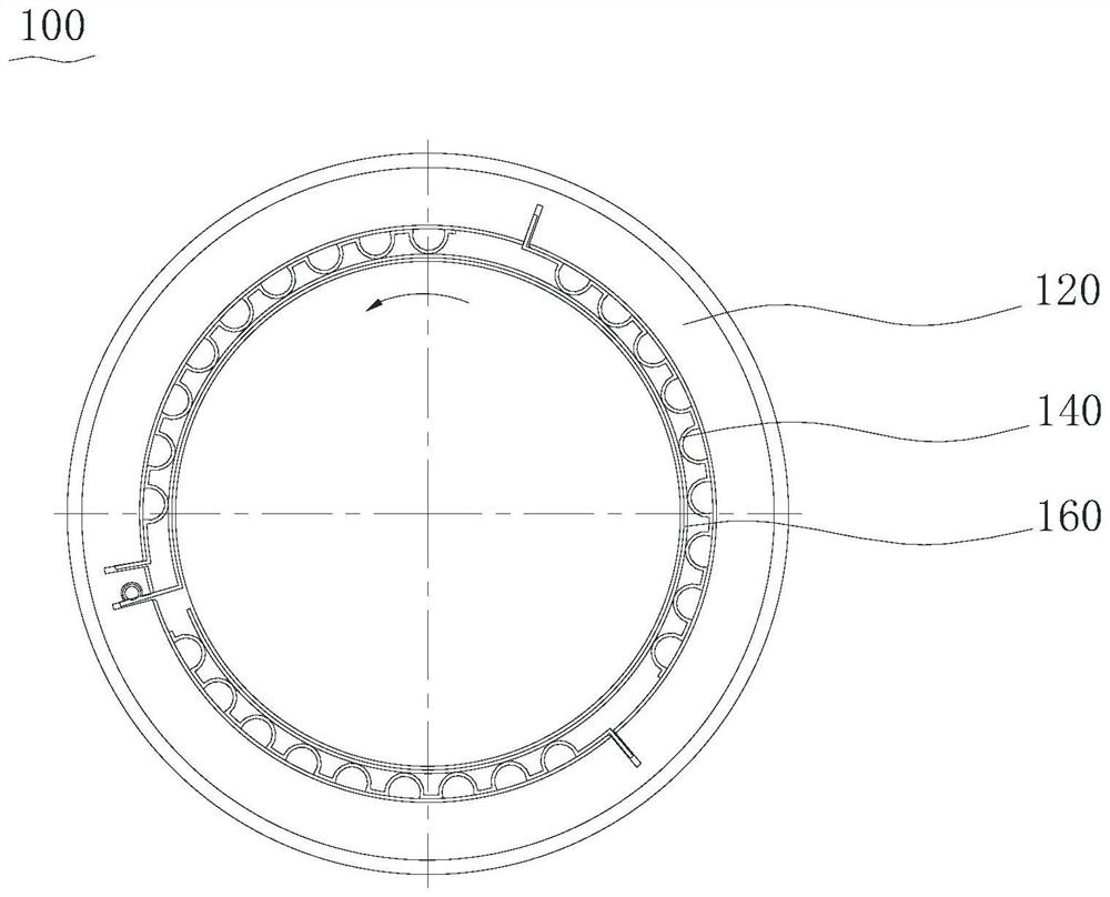
technical field [0001] The invention relates to the technical field of compressors, in particular to a rotating shaft structure, a centrifugal air compressor and a vehicle. Background technique [0002] Hydrogen fuel cell refers to a device that generates electrical energy through the chemical reaction of hydrogen with oxygen. Electric vehicles using hydrogen fuel cells are one of the breakthroughs in new energy vehicles at present. They have the advantages of high power performance, fast hydrogenation, and long cruising range. . Air compressors, as components used to provide high-pressure air sources for fuel cell systems, play an important role in hydrogen fuel cell vehicles. [0003] At present, common air compressors include centrifugal air compressors, screw air compressors and scroll air compressors. Compared with screw compressors and scroll compressors, the centrifugal air compressor is driven by the impeller to rotate the gas at a high speed, so that the gas gener...

Claims


Application Information

Patent Timeline
Patent Type & Authority Applications(China)
IPC IPC(8): F04D17/12F04D29/056F04D29/051
CPCF04D17/122F04D29/056F04D29/0513
Inventor 陈玉辉刘华张治平谭超梁湖钟瑞兴
Owner GREE ELECTRIC APPLIANCES INC
Learn More