
Mold locking mechanism of bottle blowing machine

A machine lock and mold clamping technology, which is applied to other household appliances, household appliances, household components, etc., can solve the problems of large mold rotation angle, high design requirements, and high mold closing acceleration, so as to reduce surface processing requirements and stroke Difficult design, stable and reliable operation

Pending Publication Date: 2021-12-24
JIANGSU NEWAMSTAR PACKAGING MACHINERY
View PDF0 Cites 0 Cited by
  • Summary
  • Abstract
  • Description
  • Claims
  • Application Information

AI Technical Summary

Problems solved by technology

Disadvantages: 1. There are many overlapped parts at the front of the left and right molds, and the mold must be opened at a large angle to take out the bottle; 2. The mold has a large rotation angle and poor dynamic characteristics; 3. The mold closing acceleration is large, the noise is large, and the impact is large , affecting the speed and efficiency of the blow molding machine
Disadvantages: 1. There must be a gap at the lap joint of the gusset plate, and the gusset plate must be wedged tightly by a strong spring return torque, which requires high design requirements; There is a risk of the expansion mold breaking the gusset when blowing the bottle with high-pressure air

Method used


Image

  • Mold locking mechanism of bottle blowing machine
  • Mold locking mechanism of bottle blowing machine
  • Mold locking mechanism of bottle blowing machine

Examples


Embodiment Construction

[0030] The technical solutions of the present invention will be further described below in combination with specific embodiments and accompanying drawings.

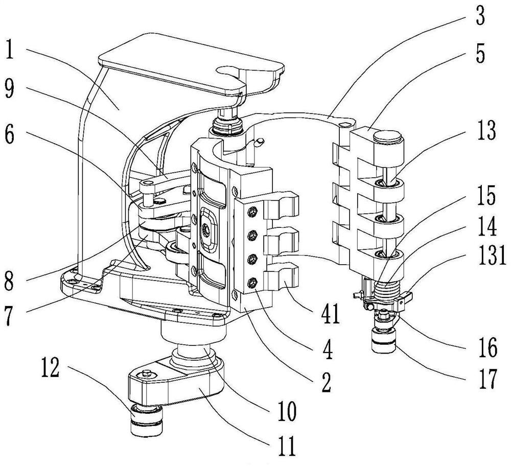
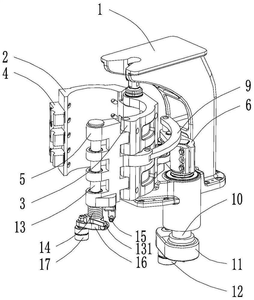
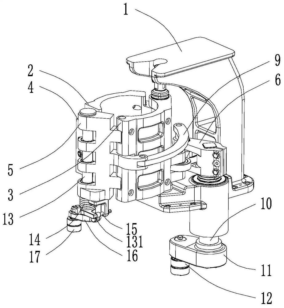
[0031] see Figure 1-7 As shown, this embodiment provides a mold clamping mechanism for a bottle blowing machine, including a mold frame bracket 1, a left mold frame 2 and a right mold frame 3 arranged on the mold frame bracket 1 that can rotate around the first axis respectively, A driving assembly arranged on the mold frame support 1 and used for driving the relative opening and closing of the left mold frame 2 and the right mold frame 3 . In this embodiment, the first axis extends along the vertical direction.

[0032] see figure 1 , 2 , 5, the left mold base 2 and the right mold base 3 are relatively open, and are in a mold-opening state; see Figure 3-4 , As shown in 6-7, the left mold base 2 and the right mold base 3 are relatively closed, and are in a mold closing state.

[0033] see figure 1 As shown, the ab...


PUM


Abstract

The invention discloses a mold locking mechanism of a bottle blowing machine. The mold locking mechanism comprises a mold frame support, a left mold frame, a right mold frame, a driving assembly, a left fastener, a right fastener and a mold locking part, wherein the left mold frame and the right mold frame can rotate around a first axis respectively and are arranged on the mold frame support; the driving assembly is arranged on the mold frame support and is used for driving a mold to be opened and closed; the left fastener is arranged on the left mold frame; the right fastener can be rotatably arranged on the right mold frame around a second axis; the mold locking part can be movably arranged on the right fastener; a locking assembly is used for locking the mold locking part on the right fastener; when the left mold frame and the right mold frame are located at the mold closing position, the left fastener and the right fastener are embedded with each other; the mold locking part is used for being hooked and propped against or separated from the left fastener when moving relative to the right fastener; the driving assembly is used for driving the right fastener to rotate relative to the right mold frame to be away from the left fastener during mold opening and further used for driving the right fastener to rotate relative to the right mold frame to be close to the left fastener during mold closing. According to the mold locking mechanism of the bottle blowing machine, a bottle can be taken out at a small mold opening angle, the rotation angle of the mold frame is small, and the dynamic characteristic is good.

Description

technical field [0001] The invention relates to the technical field of bottle blowing, in particular to a mold locking mechanism of a bottle blowing machine. Background technique [0002] The existing clamping mechanism of bottle blowing machine generally has the following two structures: [0003] One is that the front ends of the left and right molds are staggered, and the pins on one side of the mold are inserted into the holes on the other side of the mold to lock the molds on both sides; Die locked. Disadvantages: 1. There are many overlapped front ends of the left and right molds, and the mold must be opened at a large angle to take out the bottle; 2. The mold rotation angle is large, and the dynamic characteristics are poor; 3. The mold closing acceleration is large, the noise is large, and the impact is large , affecting the speed and efficiency of the blow molding machine. [0004] The other is that the pinch plate on one side of the mold is swiveled in the pinch ...

Claims


Application Information

Patent Timeline
IPC IPC(8): B29C49/56B29L22/00
CPCB29C49/56B29C2049/566B29L2031/7158
Inventor 董腾中吴书朋张晓飞于荣鹏
Owner JIANGSU NEWAMSTAR PACKAGING MACHINERY
Learn More