Oil field inspection robot based on millimeter-wave radar technology

A millimeter-wave radar and inspection robot technology, applied in the field of robots, can solve the problems of easy impurity adhesion, poor detection effect, and inability to quickly dissipate heat from the internal controller, and achieve the effects of easy blowing and heat dissipation, simple operation, and convenient use

Inactive Publication Date: 2021-12-24
深圳市中科智清新能源科技有限公司
View PDF0 Cites 0 Cited by
  • Summary
  • Abstract
  • Description
  • Claims
  • Application Information

AI Technical Summary

Problems solved by technology

[0004] The purpose of the present invention is to solve the disadvantages that the existing oil field inspection robot cannot quickly dissipate heat from the internal controller when it is in use, and its air detector is prone to impurities when detecting oil and gas, resulting in poor detection effect in the later stage , and proposed an oil field inspection robot based on millimeter wave radar technology

Method used


Image

  • Oil field inspection robot based on millimeter-wave radar technology
  • Oil field inspection robot based on millimeter-wave radar technology
  • Oil field inspection robot based on millimeter-wave radar technology

Examples


Embodiment 1

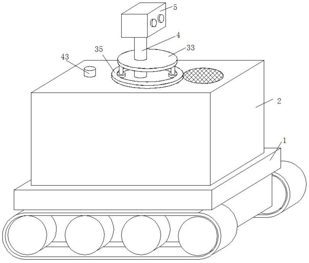
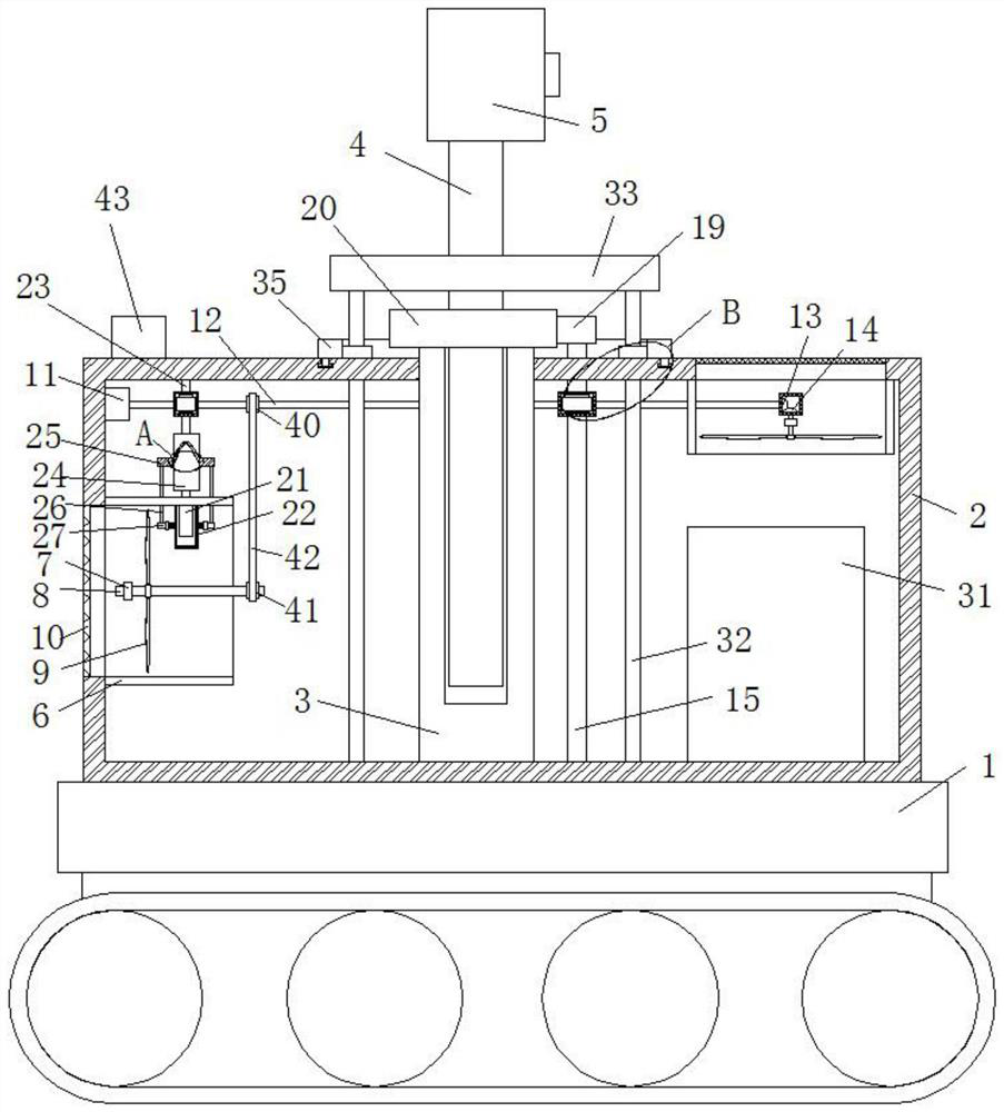
[0023] refer to Figure 1-5 , an oil field inspection robot based on millimeter-wave radar technology, including a body 1, a housing 2 is fixedly installed on the top of the body 1, a positioning column 3 is fixedly installed on the inner wall of the bottom of the housing 2, and a positioning column 3 is movably connected with Support rod 4, camera 5 is fixedly installed on the top of support rod 4, and wind guide box 6 is fixedly installed on the top inner wall and left side inner wall of housing 2, and the inner wall of air guide box 6 is provided with air guide mechanism, and housing A motor 11 is fixedly installed on the inner wall of one side of the motor 11, and a rotating rod 12 is fixedly installed on the output shaft of the motor 11. The rod 12 is connected by transmission, the bottom inner wall of the housing 2 is fixedly installed with a controller 31, the inner wall of the first air guide box 6 of the two air guide boxes 6 is fixedly installed with a detector 21, a...

Embodiment 2

[0029] refer to Figure 1-5 , an oil field inspection robot based on millimeter-wave radar technology, including a body 1, a housing 2 is fixedly installed on the top of the body 1, a positioning column 3 is fixedly installed on the inner wall of the bottom of the housing 2, and a positioning column 3 is movably connected with Support rod 4, camera 5 is fixedly installed on the top of support rod 4, and wind guide box 6 is fixedly installed on the top inner wall and left side inner wall of housing 2, and the inner wall of air guide box 6 is provided with air guide mechanism, and housing A motor 11 is fixedly installed on the inner wall of one side of the motor 11, and a rotating rod 12 is fixedly installed on the output shaft of the motor 11. The rod 12 is connected by transmission, the bottom inner wall of the housing 2 is fixedly installed with a controller 31, the inner wall of the first air guide box 6 of the two air guide boxes 6 is fixedly installed with a detector 21, a...


PUM


Abstract

The invention belongs to the technical field of robots, in particular to an oil field inspection robot based on a millimeter-wave radar technology. The oil field inspection robot based on the millimeter-wave radar technology provides the following scheme aiming at the problems that an internal controller cannot be quickly cooled when an existing oil field inspection robot is used, and when an air detector of the existing oil field inspection robot is used for detecting oil gas, impurities are easy to adhere, so that the later detection effect is poor. The oil field inspection robot comprises a robot body, a shell is fixedly installed at the top of the robot body, a positioning column is fixedly installed on the inner wall of the bottom of the shell, a supporting rod is movably connected to the positioning column, a camera is fixedly installed at the top end of the supporting rod, air guide boxes are fixedly installed on the inner wall of the top and the inner wall of the left side of the shell, and air guide mechanisms are arranged on the inner walls of the air guide boxes. The oil field inspection robot is easy to operate and convenient to use, the controller in the robot can be conveniently blown to dissipate heat, meanwhile, a filter screen outside the detector can be cleaned, the camera is driven to change the angle, and therefore the inspection range is enlarged.

Description

technical field [0001] The invention relates to the technical field of robots, in particular to an oil field inspection robot based on millimeter wave radar technology. Background technique [0002] The safety of oilfield pipelines is an important factor related to the safe production of oilfields. The prior art checks the integrated oilfield pipeline, all relying on manual work for a long time. With the rapid development of robot technology and its application in various fields, some researchers at home and abroad have begun to pay attention to introducing robot technology into the field of comprehensive oilfield pipeline inspection in recent years. Millimeter wave radar works in the millimeter wave band (millimeter wave) detection radar. Usually millimeter wave refers to the 30-300GHz frequency domain (wavelength 1-10mm). The wavelength of millimeter wave is between microwave and centimeter wave. Millimeter wave radar has some advantages of microwave radar and photoelec...

Claims


Application Information

Patent Timeline
Patent Type & Authority Applications(China)
IPC IPC(8): B25J11/00B25J19/00B25J19/02G01S13/88
CPCB25J11/00B25J19/00B25J19/023B25J19/0058B25J19/0054G01S13/88
Inventor 章斌刘浩
Owner 深圳市中科智清新能源科技有限公司
Why Eureka
Try Eureka